

High-efficiency defogging device
A defogging equipment and high-efficiency technology, which are applied in the directions of dispersed particle separation, chemical instruments and methods, separation methods, etc., can solve the problems of complex structure of the defogger, large pressure drop of the defogger, and difficulty in manufacturing, and achieve simple structure, The effect of reducing fog entrainment and not easy to scale
Active Publication Date: 2018-09-07
CHINA PETROLEUM & CHEM CORP +1
View PDF10 Cites 8 Cited by
- Summary
- Abstract
- Description
- Claims
- Application Information
AI Technical Summary
Problems solved by technology
[0006] The demister described in CN200920128824.1 is composed of a cooler, a coarse demister and a fine demister. The disadvantage of the traditional mist eliminator is that the liquid droplets flow countercurrently to the direction of the airflow, which improves the mist removal efficiency, but the structure of the mist eliminator is complex and difficult to manufacture. easy to clog
Method used
View moreImage
Smart ImageViewing Examples

Examples
Embodiment
[0061] A wet scrubber purifies flue gas 150000Nm 3 / h, wherein the apparent water concentration is 10-18g / Nm 3 , the concentration of apparent water in the exhaust gas after defogging by the present invention is less than 0.6g / Nm 3 , The defogging efficiency is greater than 94%.
Login to View More PUM
 Abstract
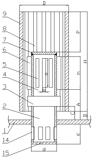
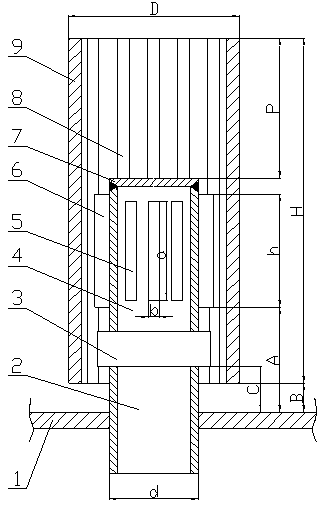
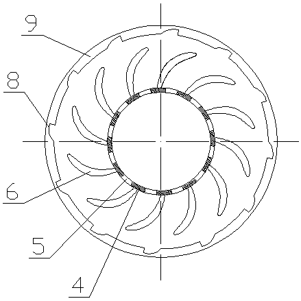
The invention discloses a high-efficiency defogging device. The high-efficiency defogging device comprises a plurality of parallel defogging components; each defogging component comprises a gas riserpipe and an outer barrel; the outer barrel is arranged on the outer side of the gas riser pipe and located on the same axis as the gas riser pipe; the gas riser pipe is axially divided into an upper part and a lower part, the upper part is a gas riser pipe I, the lower part is a gas riser pipe II, the gas riser pipe II is fixed on a tray, and the gas riser pipe I and the gas riser pipe II are connected with each other by a bearing; the top of the gas riser pipe I is provided with an upper capping plate; the gas riser pipe I is circumferentially provided with a plurality of slits; and vanes arecircumferentially arranged on the gas riser pipe I at positions close to the slits. The high-efficiency defogging device of the invention realizes the separation of droplets from gas by multiple baffling, acceleration and scraping effect in the flowing process of fluids. The high-efficiency defogging device of the invention has the advantages of simple structure, small pressure drop, small possibility of scale formation, convenient installation, reduced mist entrainment and capacity of effectively realizing gas-liquid separation, and is especially applicable to occasions with large gas flow fluctuations.
Description
technical field [0001] The invention relates to a high-efficiency defogging device, which belongs to the field of gas-liquid separation in chemical engineering and is suitable for the gas-liquid separation process in the fields of chemical engineering, environmental protection and the like. Background technique [0002] SO 2 And dust is an important cause of air pollution in my country, and it is also an air pollutant that is currently under control in our country. At present, wet process is mostly used in the field of environmental protection. In the process of wet process flue gas desulfurization, the absorption tower is easy to generate "fog" with a particle size of 10-60 microns during operation, which not only contains water, but also dissolves sulfuric acid. , sulfate, SO 2 etc., causing pollution to the atmospheric environment, and at the same time causing serious corrosion to the exhaust pipe and heat exchanger. Therefore, in the wet desulfurization process, the p...
Claims
Login to View More Application Information
Patent Timeline
 Patent Type & AuthorityApplications(China)
IPC IPC(8): B01D45/08
CPCB01D45/08
Inventor金平李欣王晶刘忠生刘淑鹤王海波王昊辰
OwnerCHINA PETROLEUM & CHEM CORP