

Non-oriented electrical steel for new energy vehicle and manufacture method thereof
A technology for new energy vehicles and grain-oriented electrical steel, which is applied in the field of non-oriented electrical steel for new energy vehicles and its production, can solve the problem that the high magnetic induction requirements of non-oriented silicon steel for new energy vehicles cannot be met, and the loss value of magnets cannot meet the requirements of new energy vehicles. Automobile use requirements, inability to meet the low iron loss requirements of non-oriented silicon steel, etc., to achieve the effect of eliminating surface corrugation defects, reducing high-temperature coiling and normalization processes, and low iron loss
- Summary
- Abstract
- Description
- Claims
- Application Information
AI Technical Summary
Problems solved by technology
Method used
Image

Examples
Embodiment 1
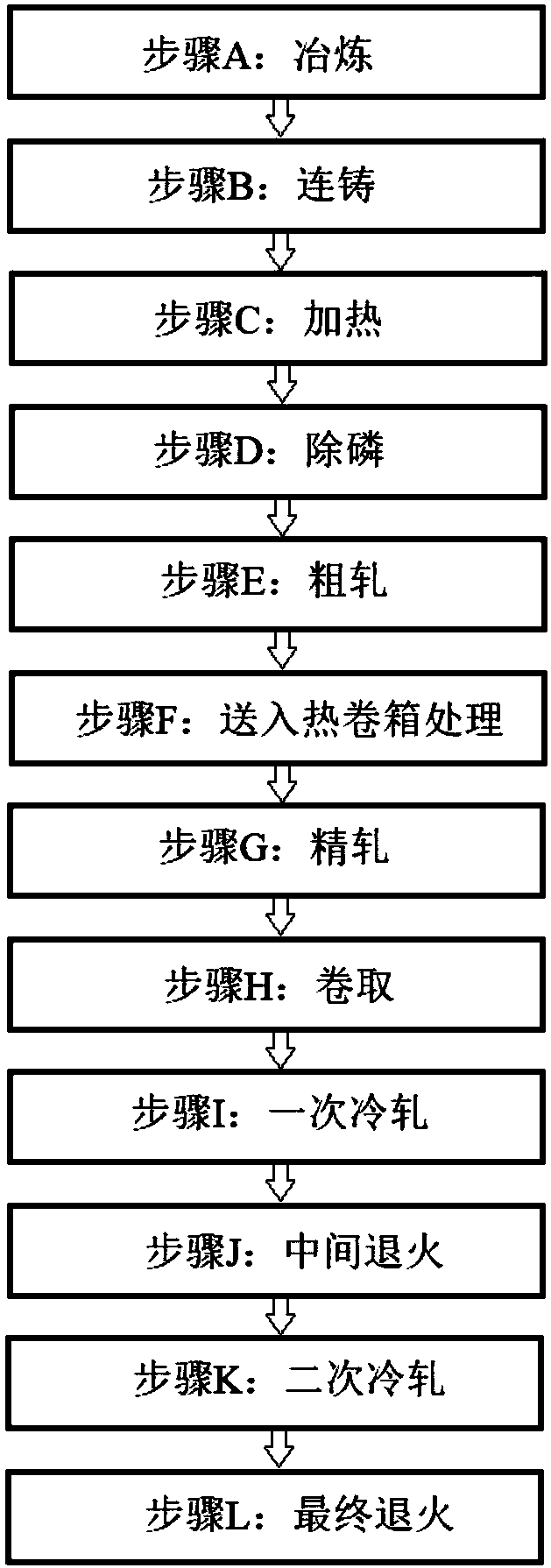
[0072] The production method of the non-oriented electrical steel for new energy vehicles of the present embodiment comprises the following steps:
[0073] Step A: smelting;
[0074] In the smelting process of step A, converter smelting is carried out first, and then RH refining treatment is carried out, and the mass percentage of the chemical composition of the end point of the molten steel after treatment is:
[0075] Si: 3.0%, Al: 2.0%, Mn: 2.0%, S: 15ppm, O: 20ppm, C: 10ppm, N: 17ppm, Ti: 8ppm, [S+O+C+N+Ti]≤80ppm, [ Sn+Sb]: 0.03%, [La+Ce+Nd]: 0.002%, the balance is Fe and other impurity elements;
[0076] Add rare earth elements 1 minute after RH refining and alloying, and stir after adding rare earth elements for 3.5 minutes;
[0077] Step B: continuous casting;
[0078] In the continuous casting process of step B, the casting speed is controlled to be 0.6 m / min during continuous casting, and a slab with a thickness of 220 mm is obtained through continuous casting; ele...
Embodiment 2
[0099] The production method of the non-oriented electrical steel for new energy vehicles of the present embodiment comprises the following steps:
[0100] Step A: smelting;
[0101] In the smelting process of step A, converter smelting is carried out first, and then RH refining treatment is carried out, and the mass percentage of the chemical composition of the end point of the molten steel after treatment is:
[0102] Si: 3.5%, Al: 1.5%, Mn: 1.5%, S: 12ppm, O: 15ppm, C: 10ppm, N: 15ppm, Ti: 5ppm, Sn: 0.05%, La: 0.005%, the balance is Fe and Other impurity elements;
[0103] Add rare earth elements 2 minutes after RH refining and alloying, and stir after adding rare earth elements for 3 minutes;
[0104] Step B: continuous casting;
[0105] In the continuous casting process of step B, the casting speed is controlled to be 1.0 m / min during continuous casting, and a slab with a thickness of 250mm is obtained through continuous casting; electromagnetic stirring is used in the...
Embodiment 3
[0126] The production method of the non-oriented electrical steel for new energy vehicles of the present embodiment comprises the following steps:
[0127] Step A: smelting;
[0128] In the smelting process of step A, converter smelting is carried out first, and then RH refining treatment is carried out, and the mass percentage of the chemical composition of the end point of the molten steel after treatment is:
[0129] Si: 4.0%, Al: 1.0%, Mn: 1.0%, S: 18ppm, O: 12ppm, C: 10ppm, N: 15ppm, Ti: 5ppm, Sb: 0.1%, [La+Ce]: 0.1%, Yu The amount is Fe and other impurity elements;
[0130] Add rare earth elements 2 minutes after RH refining and alloying, and stir after adding rare earth elements for 4 minutes;
[0131] Step B: continuous casting;
[0132] In the continuous casting process of step B, the casting speed is controlled to be 2.0 m / min during continuous casting, and a slab with a thickness of 300 mm is obtained through continuous casting; electromagnetic stirring is used i...
PUM
 Abstract
Description
Claims
Application Information