Differential confocal discrete fluorescence spectrum and fluorescence lifetime detection method and device

A differential confocal and fluorescence lifetime technology, which is applied in the field of chemical substance detection, can solve problems such as inability to ensure consistent excitation beam spot size, inability to maintain consistent resolution of the detection system, and inability to obtain fluorescence distribution imaging on the sample surface. The effects of limited measurement accuracy, high identification speed and identification accuracy, and convenient detection process

Inactive Publication Date: 2018-09-07
杨佳苗
View PDF6 Cites 7 Cited by
  • Summary
  • Abstract
  • Description
  • Claims
  • Application Information

AI Technical Summary

Problems solved by technology

[0004] However, in the process of scanning and imaging the surface excited fluorescence of the sample to be tested, when the surface of the sample to be tested is uneven, it is impossible to ensure that the spot size of the excitation beam at different positions on the surface of the sample to be tested is consistent, which leads to the detection system at different positions. The resolution cannot be kept consistent
Especially for some samples with large fluctuations, there is even the possibility that the objective lens collides with the sample to be measured during the sample scanning process due to the small working distance of the system measurement objective lens. In the end, not only the fluorescence distribution imaging on the sample surface cannot be obtained, but also the system will cause The surface of the objective lens is contaminated

Method used


Image

  • Differential confocal discrete fluorescence spectrum and fluorescence lifetime detection method and device
  • Differential confocal discrete fluorescence spectrum and fluorescence lifetime detection method and device
  • Differential confocal discrete fluorescence spectrum and fluorescence lifetime detection method and device

Examples


Embodiment 1

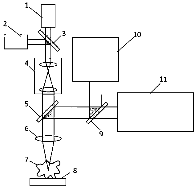
[0043] The problem to be solved in this embodiment is to simultaneously scan the three-dimensional shape of the sample to be tested and analyze the spatial distribution of the tumor tissue in the sample to be tested, and judge the boundary information of the tumor tissue accordingly. In this embodiment, a confocal detection system is used to measure the three-dimensional shape, and the fluorescence lifetimes of the four wavelengths of 400 nm, 450 nm, 530 nm and 580 nm excited by the 355 nm wavelength pulsed laser in the sample are used to judge each scan Whether the point is a tumor cell or not. Since the fluorescence signal of the sample is very weak, this embodiment uses a photomultiplier tube as a light intensity sensor for fluorescence detection to improve the fluorescence light intensity detection sensitivity of the system.

[0044] Figure 9 It is a specific implementation device for realizing differential confocal discrete fluorescence spectroscopy and fluorescence lif...

Embodiment 2

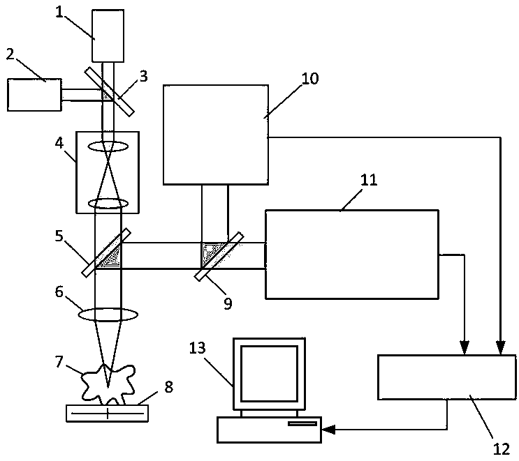
[0054] Different from Embodiment 1, this embodiment utilizes the difference in spectral intensity of fluorescence to determine whether each point on the surface of the sample 7 to be tested is a tumor tissue or a normal tissue. The device used and the sample to be tested are the same as in Example 1. In order to improve the stability of the fluorescence spectrum measurement, the present embodiment uses the light beam emitted by the continuous laser light source 2 to excite the sample 7 to be tested to generate fluorescence, and the measurement steps are as follows:

[0055] (a) Turn on the continuous laser light source 2, and move the sample 7 to be measured to the starting position of the transverse scanning along the x and y directions ( x 1 , y 1 ), and then scan the sample 7 to be tested along the z direction at this position. Using the differential confocal detection system 10, measure the post-focus light intensity response curve as the scanning position changes I ...

Embodiment 3

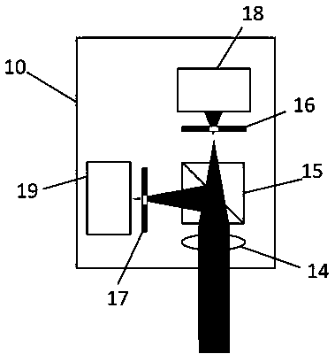
[0061] Different from Example 1, as attached Figure 5 As shown, in order to improve the resolution of the detection beam, a converging lens and a pinhole are respectively added in front of all the light intensity sensors of the discrete fluorescence spectrum and fluorescence lifetime detection system 11 . The pinhole is placed at the focus position of the converging lens, and the converging lens converges the fluorescent light beams of different wavelengths to perform spatial filtering through the pinhole. Therefore, the fluorescent signals detected by each light intensity sensor are the filtered fluorescent light intensity information, and these filtered fluorescent lights accurately correspond to the fluorescent signals excited by the focal point of the detection beam, and the fluorescent signals outside the focal point are effectively analyzed. shield.


PUM

PropertyMeasurementUnit
wavelengthaaaaaaaaaa

Abstract

The invention belongs to the technical field of chemical substance detection and relates to a differential confocal discrete fluorescence spectrum and fluorescence lifetime detection method and device. The basic thought is that a differential confocal object surface positioning technology with a precision axial resolution ratio and a discrete fluorescence spectrum and fluorescence lifetime measurement technology are fused; high-precision measurement of a three-dimensional shape of the surface of a sample to be detected is solved by utilizing a differential confocal technology; meanwhile, high-sensitivity detection of a fluorescence spectrum and fluorescence lifetime of each point on the surface of the sample to be detected is solved by utilizing the discrete fluorescence spectrum and fluorescence lifetime measurement technology, so that three-dimensional high-resolution space substance component distribution information is obtained. According to the differential confocal discrete fluorescence spectrum and fluorescence lifetime detection method and device, a differential confocal measurement technology and a fluorescence substance component detection technology are fused for the first time; a fluorescence imaging system has the same transverse resolution ratio on each position of the surface of the sample to be detected; finally, measured fluorescence spectrum distribution accurately corresponds to the three-dimensional shape. The technology provided by the invention has a wide application prospect in the fields of biological science, medical science, material science and clinical medical diagnosis.

Description

technical field [0001] The invention belongs to the technical field of chemical substance detection. It can not only identify the components of substances with high sensitivity, but also detect the spatial distribution of the components of substances. It will play an important role in the research fields of biology, medicine, material science and clinical medical diagnosis. application. Background technique [0002] In the fields of biology, physics, chemistry and materials, spectral detection and analysis has become a basic measurement method for basic research due to its very high sensitivity, molecular specificity and non-contact measurement characteristics. Among them, fluorescence spectrum detection is a method for qualitative and quantitative analysis of substances by using the characteristics and intensity of fluorescence produced by substances under ultraviolet light irradiation. Especially for most organic compounds, the fluorescence produced by them usually has st...

Claims


Application Information

Patent Timeline
Patent Type & Authority Applications(China)
IPC IPC(8): G01N21/64G01N21/01G01B11/24
CPCG01B11/24G01N21/01G01N21/6402
Inventor 杨佳苗李静伟龚雷
Owner 杨佳苗
Why Eureka
Try Eureka