Precise constant flow source based on differential amplifier and feedback buffer

A differential amplifier and buffer technology, applied in the field of precision constant current sources, can solve the problems of low precision and high input impedance of resistance consistency amplifiers, and achieve the effects of high precision, low power consumption, and reduced temperature drift

Pending Publication Date: 2018-09-07
INST OF CHEM MATERIAL CHINA ACADEMY OF ENG PHYSICS
View PDF0 Cites 7 Cited by
  • Summary
  • Abstract
  • Description
  • Claims
  • Application Information

AI Technical Summary

Problems solved by technology

[0003] The purpose of the present invention is to provide a precision constant current source based on a differential amplifier and a feedback buffer, which is used to solve the inaccuracy of the traditional voltage-controlled constant current source caused by the consistency of resistance and the high input impedance of the amplifier in the prior art. high problem

Method used


Image

  • Precise constant flow source based on differential amplifier and feedback buffer
  • Precise constant flow source based on differential amplifier and feedback buffer
  • Precise constant flow source based on differential amplifier and feedback buffer

Examples


Embodiment 1

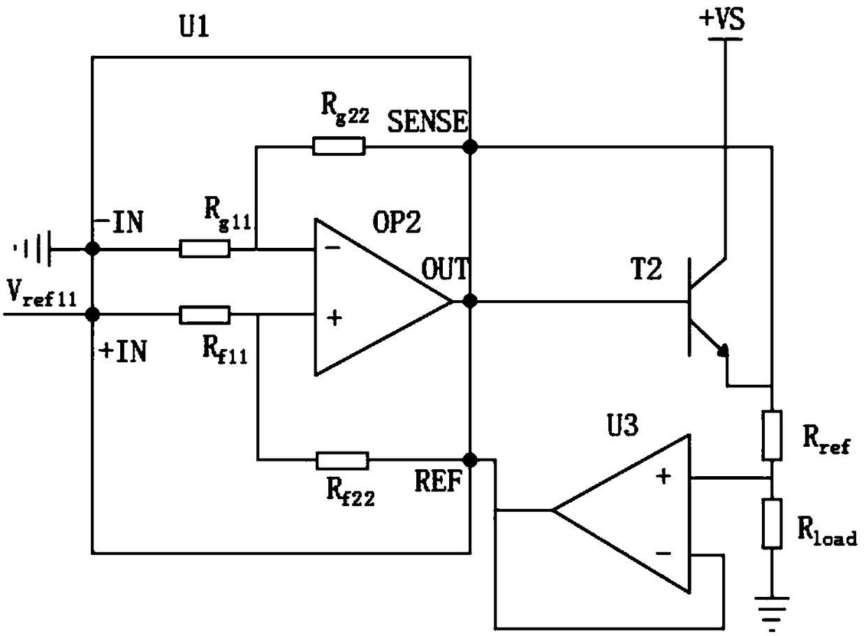
[0024] combined with figure 1 As shown, a precision constant current source based on a differential amplifier and a feedback buffer, including a differential amplifier U1 integrating an amplifier, an input resistor and a feedback resistor, a feedback buffer U3, a transistor T2, and a resistor R ref and resistor R load , the positive input terminal of the differential amplifier U1 is connected to the reference voltage output circuit U2, the negative input terminal of the differential amplifier U1 is grounded, the output terminal of the differential amplifier U1 is connected to the base of the triode T2, and the emitter of the triode T2 Connect the SENSE terminal of the differential amplifier U1 and serially connect the resistors R ref and resistor R load After grounding, the voltage feedback input terminal of the differential amplifier U1 is connected to the output terminal and the negative input terminal of the feedback buffer U3, and the resistor R ref and resistor R load...

Embodiment 2

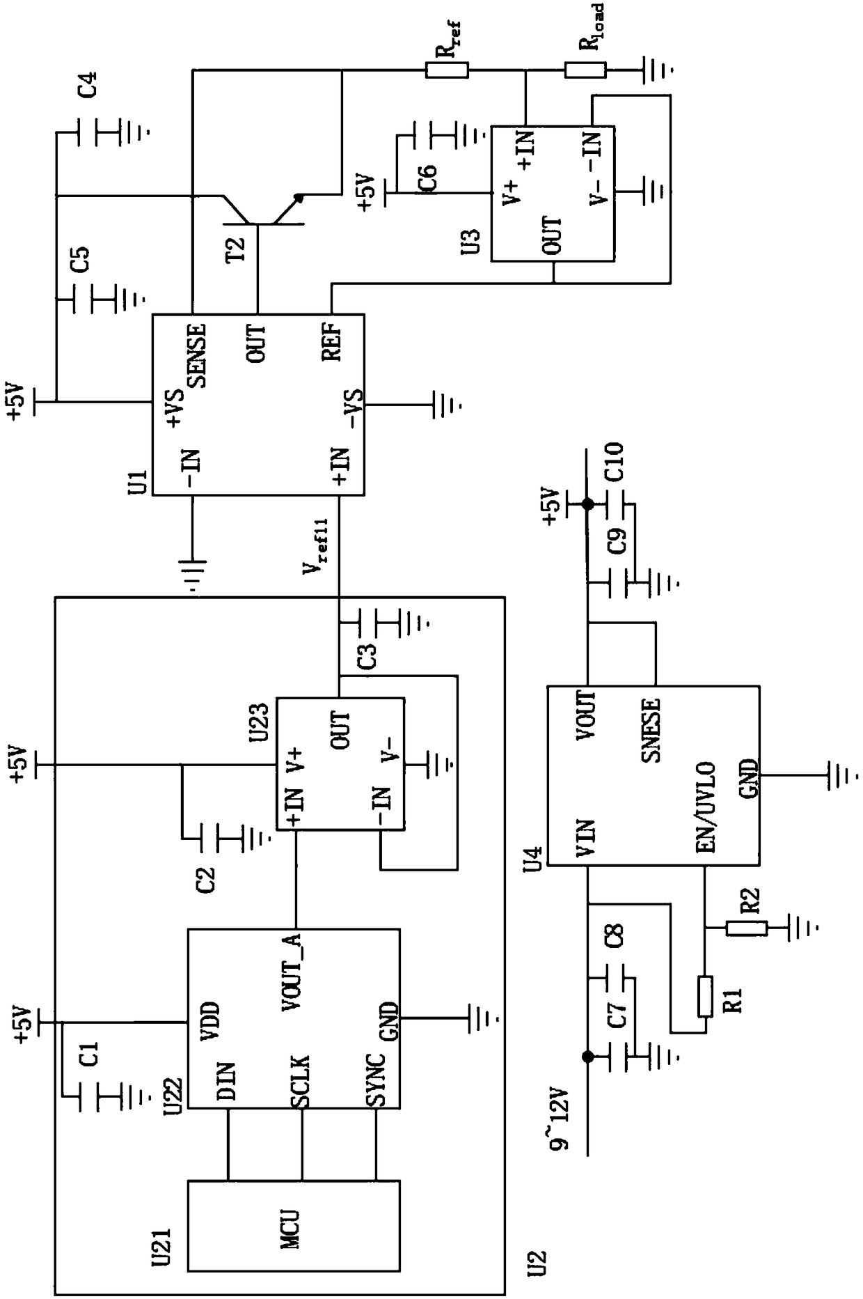
[0028] On the basis of Example 1, combined with figure 2 As shown, the reference voltage output circuit U2 includes a control chip U21, a digital-to-analog converter U22, and an operational amplifier U23 connected in sequence, and the output terminal of the operational amplifier U23 is connected to the positive input terminal of the differential amplifier U1. The power supply circuit that provides voltage for the transistor T2, the differential amplifier U1, the feedback buffer U3 and the reference voltage input circuit U2 includes a CMOS linear voltage regulator U4, and the voltage input terminal of the CMOS linear voltage regulator U4 is connected to the filter circuit Connected with the battery, the voltage output terminal of the CMOS linear regulator U4 is respectively connected with the reference voltage output circuit U2, the differential amplifier U1, the voltage input terminal of the feedback buffer U3 and the collector of the triode T2.

[0029] The power supply circ...


PUM


Abstract

The invention discloses a precise constant flow source based on a differential amplifier and a feedback buffer. The precise constant flow source comprises an amplifier, an input resistor-feedback resistor integrated differential amplifier, a feedback buffer, a triode T2, a resistor Rref and a resistor Rload, wherein a reference voltage output circuit is connected to a positive input end of the differential amplifier, a negative input end of the differential amplifier is connected to the ground, an output end of the differential amplifier is connected to a base electrode of a triode T2, an emitting electrode of the triode T2 is connected with a SENSE wiring end of the differential amplifier, is sequentially connected to the resistor Rref and the resistor Rload and is connected to the ground, an voltage feedback input end of the differential amplifier is connected with an output end and negative input end of the feedback buffer, and a node between the resistor Rref and the resistor Rloadis connected with a positive input end of the feedback buffer. According to the precise constant flow source, the coherence of peripheral resistances is improved by virtue of the differential amplifier, and a current output loop and a voltage feedback circuit are isolated by virtue of the feedback buffer, so that the input impedance relative to outside of the differential amplifier is increased,and the current of the constant flow source is more accurate.

Description

technical field [0001] The invention relates to the technical field of precision constant current sources, in particular to a precision constant current source based on a differential amplifier and a feedback buffer. Background technique [0002] Precision constant current sources are required in many applications, including industrial process control, instrumentation, medical equipment, and consumer electronics, to name a few. For example, process control systems use constant current sources to provide the excitation current required by resistance temperature detectors; digital multimeters use constant current sources to measure resistance, capacitance, and diodes; long-distance information transmission systems use constant current sources to drive communication current loops. The quality of the constant current source directly determines the overall performance of these systems. Traditional constant current sources are basically constructed with operational amplifiers, re...

Claims


Application Information

Patent Timeline
Patent Type & Authority Applications(China)
IPC IPC(8): G05F1/56
CPCG05F1/56
Inventor 刘琦谢尧尧刘瑜嘉刘斌董明陆蔺辉王晓强谢德王精
Owner INST OF CHEM MATERIAL CHINA ACADEMY OF ENG PHYSICS
Why Eureka
Try Eureka