A reciprocating sequence valve and its sequence driving method
A sequential valve, reciprocating technology, applied in the field of hydraulic valves, can solve the problem of not being able to reciprocate twice in sequence at one time, so as to improve combustion efficiency and quality, increase fuel injection pressure, and reduce zero. The effect of the number of parts
- Summary
- Abstract
- Description
- Claims
- Application Information
AI Technical Summary
Problems solved by technology
Method used
Image
Examples
Embodiment 1
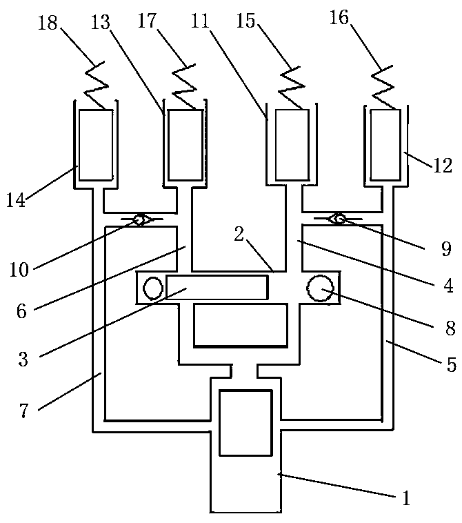
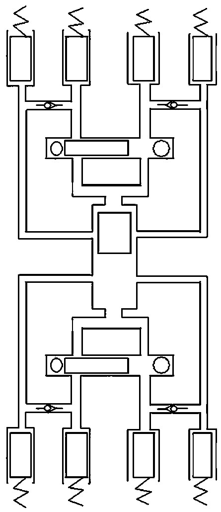
[0042] Embodiment 1: Reciprocating two-position four-action sequence valve.
[0043] Such as figure 1 As shown, the reciprocating sequence valve of the present invention includes a reciprocating single-acting plunger cylinder 1, a negative pressure shuttle valve 2, a second hydraulic cylinder group and a first hydraulic cylinder group.
[0044] The plunger cylinder 1 includes a cylinder body and a plunger arranged inside the cylinder body, and the plunger and the cylinder wall form a seal at all coupling sections to avoid oil leakage. The top of the cylinder body is opened to form an end oil passage, and a side wall oil passage is provided on the side cylinder wall of the cylinder body. When in use, the plunger in the plunger cylinder 1 can be synchronously linked with the piston of the internal combustion engine in the same direction to provide power for the sequence valve.
[0045] The shuttle valve 2 includes a housing and a valve core 3 arranged inside the housing. The v...
Embodiment 2
[0051] Embodiment 2: Sequential driving method of reciprocating sequence valve.
[0052] The sequence driving method of the re-entry sequence valve of the present invention comprises the following steps:
[0053] 1. Set the reentry sequence valve as described in Embodiment 1. When the machine is shut down, the spool 3 of the negative pressure shuttle valve 2 is located on the left side of the inner cavity of the valve body, and the right oil port connected to the first oil pipe 4 is in the In the open state, the left oil passage connected to the third oil pipe 6 is in the closed state.
[0054] 2. The plunger in the plunger cylinder 1 is controlled to go upward, and the hydraulic oil enters the first hydraulic cylinder 11 through the end oil port, the shuttle valve 2 and the first oil pipe 4 (because the third oil pipe 6 is blocked at this time), And push the piston in the first hydraulic cylinder 11 to act upwards (because the activation pressure of the second reset device 1...
Embodiment 3
[0060] Embodiment 3: The method of using the double-position two-position four-action sequence valve on an internal combustion engine.
[0061] The method for using a reciprocating sequence valve on an internal combustion engine comprises the following steps:
[0062]1. The re-entry sequence valve described in Embodiment 1 is installed on the internal combustion engine, the plunger in the plunger cylinder 1 and the piston of the internal combustion engine are synchronously linked in the same direction, and the first reset device 15 is linked with the first group of valves of the internal combustion engine , the second reset device 16 is linked with the first group of fuel pump plungers of the internal combustion engine, the third reset device 17 is linked with the second group of valves of the internal combustion engine, and the fourth reset device 18 is linked with the second group of fuel pump plungers of the internal combustion engine; stop , the spool 3 of the negative pre...
PUM
 Abstract
Description
Claims
Application Information
 - R&D
- Intellectual Property
- Life Sciences
- Materials
- Tech Scout
- Unparalleled Data Quality
- Higher Quality Content
- 60% Fewer Hallucinations
Browse by: Latest US Patents, China's latest patents, Technical Efficacy Thesaurus, Application Domain, Technology Topic, Popular Technical Reports.
© 2025 PatSnap. All rights reserved.Legal|Privacy policy|Modern Slavery Act Transparency Statement|Sitemap|About US| Contact US: help@patsnap.com


