Electric automobile two-way wireless charging system transmission power control method

An electric vehicle and wireless charging technology, applied in electric vehicle charging technology, electric vehicles, charging stations, etc., can solve the problems of high system cost, unknown and uncontrollable external phase shift angle γ

Active Publication Date: 2018-09-18
TSINGHUA UNIV
View PDF5 Cites 21 Cited by
  • Summary
  • Abstract
  • Description
  • Claims
  • Application Information

AI Technical Summary

Problems solved by technology

[0013] There are two control methods for the existing BWCS system: 1) The converter on one side operates in the high-frequency inverter mode, and the converter on the other side operates in the uncontrolled rectification mode. Only by adjusting α (adjusting β in discharge mode) , to control the transmission power of the system, the main problem is that it is impossible to ensure that the transmission power reaches the command value P ref While ensuring that the voltage gain satisfies the constraints 2) By adding an auxiliary coil in addition to the secondary coil, it is used to obtain the phase of the primary coil current after making a difference with the secondary coil current, and by tracking the primary current phase to ensure that the external phase angle γ is maintained at π/2 (or 3π/2), the main problem is that this method relies on the accurate sampling of the phase difference between the high-frequency current in the primary and secondary coils

Method used


Image

  • Electric automobile two-way wireless charging system transmission power control method
  • Electric automobile two-way wireless charging system transmission power control method
  • Electric automobile two-way wireless charging system transmission power control method

Examples


Embodiment Construction

[0058] The embodiments will be described in detail below in conjunction with the accompanying drawings.

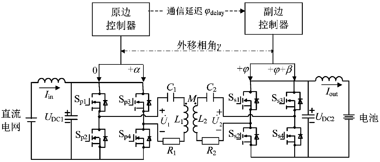
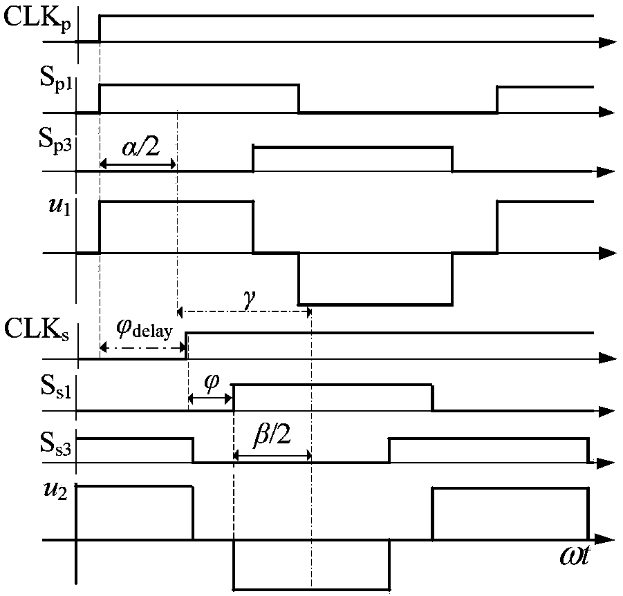
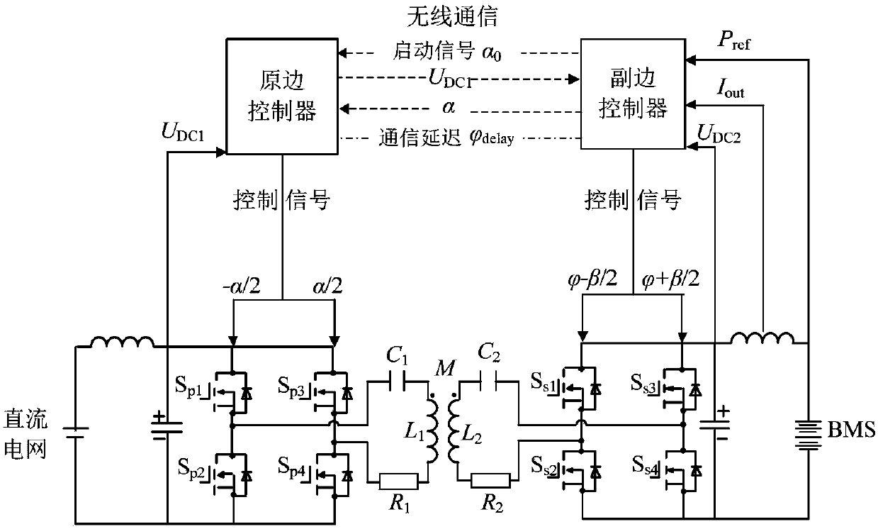
[0059] In view of the above-mentioned BWCS control requirements and the difficulties in the existing technology, the purpose of the present invention is to propose a BWCS transmission power control that does not depend on the accurate sampling of high-frequency current and is not affected by the delay of the primary and secondary wireless communication. Control Strategy. The information interaction process of the primary and secondary converters is as follows: image 3 As shown, the overall control block diagram is shown as Figure 4 shown. To ensure that the system voltage gain satisfies the constraints as much as possible Under the premise that the transmission power is controlled through power prediction, the BWCS system can maintain a high transmission efficiency in the full power range.

[0060] 1. The start-up process of the primary side converter

[0061] The ...


PUM


Abstract

The invention belongs to the technical field of wireless charging and particularly relates to an electric automobile two-way wireless charging system transmission power control method. The method includes the following steps that the mutual inductance between a primary coil and an secondary coil of a system is calculated, and an inward-shifting phase angle of a primary convertor and a secondary convertor is obtained through calculation according to an output power command value; a primary controller and a secondary controller correspondingly adjust the phases of bridge arm switching signals inthe primary convertor and the secondary convertor with corresponding clock signals as standards, and control over the direction and the size of the transmission power is uncoupled; and the extreme value of the output current is tracked, so that the phases of control signals of the primary convertor and the secondary convertor are synchronous, and the direction of the system transmission power iscontrolled. The problem that an outward-shifting phase angle is unknowable and uncontrollable due to communication delay is solved, control over the direction and the size of the transmission power isuncoupled, phase information of the high-frequency current in the primary coil and the secondary coil is not needed, the circuit design difficulty and the requirement for the arithmetic speed are reduced, cost is reduced, and anti-interference performance and reliability are improved.

Description

technical field [0001] The invention belongs to the technical field of wireless charging, and in particular relates to a transmission power control method of a two-way wireless charging system for an electric vehicle. Background technique [0002] Wireless Power Transfer (WPT) technology has been widely used in smart phones, medical equipment, electric vehicles, industrial automation and other fields. Compared with traditional wired charging, the two-way wireless charging system is more suitable for the application of vehicle to grid (V2G) than wired charging because of its characteristics of no plug-in and unplugging, instant charging, and flexibility. The two-way flow of power between power grids has strong advantages in peak shaving and valley filling, no-load backup, peak power adjustment, and automatic power generation control. [0003] The control object is the bidirectional wireless charging system (Bidirectional Wireless Charging System, BWCS) of electric vehicles, ...

Claims


Application Information

Patent Timeline
IPC IPC(8): B60L11/18H02J7/00H02J3/32H02J50/12H02J5/00
CPCB60L53/12H02J3/32H02J5/005H02J7/025H02J50/12Y02T10/70Y02T10/7072Y02T90/14
Inventor 刘方陈凯楠赵争鸣檀添蒋烨袁立强
Owner TSINGHUA UNIV
Why Eureka
Try Eureka