Thermoelectric device with adaptive connection layer

A technology of thermoelectric devices and connecting layers, applied in the direction of thermoelectric devices that only utilize the Peltier or Seebeck effect

Pending Publication Date: 2018-09-18
SHANGHAI INST OF CERAMIC CHEM & TECH CHINESE ACAD OF SCI
View PDF5 Cites 1 Cited by
  • Summary
  • Abstract
  • Description
  • Claims
  • Application Information

AI Technical Summary

Problems solved by technology

Obviously, the current research work is mainly focused on reducing the interface stress between the thermoelectric material and the high-temperature end electrode in a single thermoelectric element, and between a single thermoelectric element and a high-temperature end guide plate, but at the level of thermoelectric pairs and thermoelectric devices, the above-mentioned The study does not help to relieve interfacial stresses caused by differences in thermal expansion coefficients between n-type and p-type elements, and between baffles on the high temperature side and metallized ceramic substrates on the low temperature side

Method used


Image

  • Thermoelectric device with adaptive connection layer
  • Thermoelectric device with adaptive connection layer

Examples


Embodiment 1

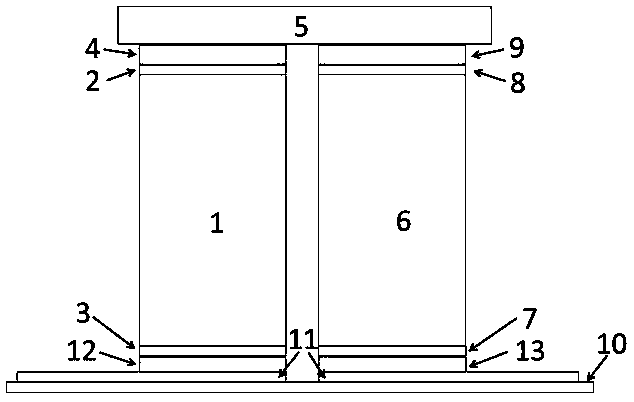
[0044] N-type and p-type skutterudite samples with a barrier layer and an electrode were sintered with a diameter of 50 mm and a thickness of 8 mm by a one-step sintering process, and their structures were Ni / Ti-Al / Yb, respectively 0.3 co 4 Sb 12 / Ti-Al / Ni and Ni / Ti-Al / CeFe 4 Sb 12 / Ti-Al / Ni, where Ni is the electrode with a thickness of about 120 μm, and Ti-Al is the barrier layer with a thickness of about 100 μm. The corresponding thermoelectric element is obtained by wire cutting, and the size is 4*4*8mm 3 . Then through the brazing process, with the help of Cu-Ag solder, the high temperature ends of the above n-type and p-type components are passed through with a size of 5*12*2mm 3 The Mo-Cu baffles are rigidly connected to obtain the corresponding thermoelectric pair;

[0045] The circuit design of the cold end of the thermoelectric device is carried out, and the appropriate copper-clad ceramic substrate is selected accordingly, so that a thermoelectric device compo...

Embodiment 2

[0052] Referring to the steps of Example 1, a thermoelectric device C consisting of 8 thermoelectric pairs connected in series with each interface rigidly connected was prepared. As a comparison, 8 thermoelectric pairs were randomly selected, and the copper-clad ceramic substrate and the cold ends of the thermoelectric pairs were ultrasonically cleaned and dried. Place the surface of the copper-clad ceramic substrate on the heating platform, with the copper-clad side facing up. The size of 4*4*0.02mm is placed on the surface of the copper clad layer of the substrate corresponding to the cold end of the n-type and p-type components. 3 The In foil (thickness is 300 μm) and Sn foil (thickness is 300 μm), the cold end of the thermoelectric pair n-type thermoelectric element and the p-type thermoelectric element are placed on the In foil and the Sn foil respectively, and 0.01 is applied to the cold end of the thermoelectric pair. ~0.5MPa pressure and maintain. Turn on the heating...


PUM

PropertyMeasurementUnit
thicknessaaaaaaaaaa
thicknessaaaaaaaaaa
thicknessaaaaaaaaaa

Abstract

The present invention provides a thermoelectric device with an adaptive connection layer. The thermoelectric device comprises a substrate and at least one thermoelectric pair which is connected to thesubstrate and composed of an n-type thermoelectric element, a p-type thermoelectric element, and a flow deflector for connecting the n-type thermoelectric element and the p-type thermoelectric element; a high temperature end of the n-type thermoelectric element and/or the p-type thermoelectric element is connected with the flow deflector through a first adaptive connection layer, and/or a low temperature end of the n-type thermoelectric element and/or the p-type thermoelectric element is connected with the substrate through a second adaptive connection layer; and the composition of the firstadaptive connection layer and/or the second adaptive connection layer is selected from a simple substance consisting of In, Ga, Cu, Al, Ag, Au, Li, Na, K, Ge and Te or any at least two formed alloys.

Description

technical field [0001] The invention relates to a thermoelectric device with an adaptive connection layer, belonging to the technical field of thermoelectric materials and devices. Background technique [0002] Using the Seebeck effect of thermoelectric materials, the temperature difference between the hot and cold ends of thermoelectric materials can be directly converted into electrical energy. The thermoelectric power generation system based on this principle has simple structure, compact layout, no rotating / transmission parts and working fluid, and can work statically for a long time. It has broad application prospects in the fields of deep space exploration, special power supply and waste heat power generation. [0003] The thermoelectric performance of materials is expressed by the dimensionless thermoelectric figure of merit ZT, and high ZT peak value is the primary goal of thermoelectric material research. The ZT value usually changes with temperature. Based on the ...

Claims


Application Information

Patent Timeline
Patent Type & Authority Applications(China)
IPC IPC(8): H01L35/28H01L35/32
CPCH10N10/10H10N10/17
Inventor 顾明夏绪贵廖锦城柏胜强刘睿恒吴汀宋君强陈立东
Owner SHANGHAI INST OF CERAMIC CHEM & TECH CHINESE ACAD OF SCI
Why Eureka
Try Eureka