Piston-cylinder refrigerating device based on memory alloy thermoelastic effect

A memory alloy and refrigeration device technology, applied in piston pumps, refrigerators, refrigeration components, etc., can solve the problems of unfavorable heat controllable transmission, free heat loss, and low heat exchange efficiency, so as to improve circulation rate and reduce natural loss , Improve the effect of heat transfer rate

Pending Publication Date: 2018-09-21
UNIV OF SCI & TECH BEIJING
View PDF14 Cites 19 Cited by
  • Summary
  • Abstract
  • Description
  • Claims
  • Application Information

AI Technical Summary

Problems solved by technology

These refrigeration devices are not only bulky and have low heat exchange efficiency, but also the open structure makes heat loss serious, which is not conducive to the controllable transmission of heat.

Method used


Image

  • Piston-cylinder refrigerating device based on memory alloy thermoelastic effect

Examples


specific Embodiment approach 1

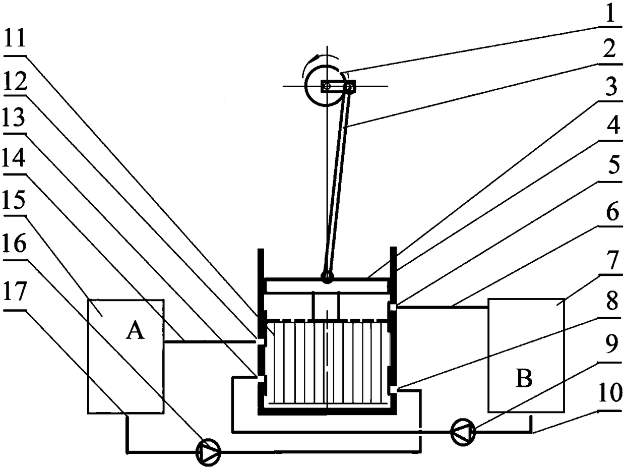
[0021] Step 1, install the motor power system. The output shaft of the motor (1) is perpendicular to the central axis of the hydraulic cylinder (4). One end of the crank connecting rod (2) is installed on the output shaft of the motor, and the other end is installed on the top of the piston (3), and the two ends of the crank connecting rod are hinged. The rotary motion of the output shaft of the motor is converted into the linear reciprocating motion of the piston in the hydraulic cylinder through the crank connecting rod. The frequency of the linear reciprocating motion of the piston is adjusted by the motor speed, and the stroke of the linear reciprocating motion of the piston is adjusted by the eccentricity of the crank connecting rod. The stroke of the linear reciprocating motion of the piston is selected as 30 mm. Adjust the distance between the motor and the hydraulic cylinder so that when the connecting rod is at the lowest position, the space height between the lower...

specific Embodiment approach 2

[0025] The difference between this embodiment and the first embodiment is that the loading method of the memory alloy is compression loading. The memory alloy thermoelastic effect cooling body is processed into a compression spring, and the free length of the spring is 60mm. Adjust the distance between the motor and the hydraulic cylinder so that when the connecting rod is at the highest position, the space height between the lower surface of the piston and the inner bottom surface of the hydraulic cylinder is 60mm.

[0026] Correspondingly, when the piston is in the second half cycle, the memory alloy compression spring induces martensitic phase transformation, releasing the latent heat of phase transformation. Along with refrigeration system operation, the water temperature in A container (15) constantly reduces, and the water temperature in B container (7) raises gradually.


PUM

PropertyMeasurementUnit
lengthaaaaaaaaaa
lengthaaaaaaaaaa

Abstract

A piston-cylinder refrigerating device based on memory alloy thermoelastic effect belongs to the technical field of refrigeration and comprises a motor power system, a memory alloy thermoelastic effect refrigerator, and a dual-circuit controllable liquid-flow heat exchange system. A motor drives a piston to linearly reciprocate in a hydraulic cylinder. Memory alloy is arranged in space between thepiston and the bottom of the hydraulic cylinder; reciprocating of the piston enables the memory alloy to periodically deform by loading and restore by unloading, and alternate martensite phase-changeheat release and inverse-change heat absorption are generated correspondingly. A piston spool and holes in the sidewall of the hydraulic cylinder form two pairs of spool inlets and two pairs of spooloutlets; when the piston moves during upper and lower half cycles, one pair of spool inlets and one pair of spool outlets are opened, one heat exchange flow is controlled to enter the hydraulic cylinder and exchange with heat with the memory alloy; after the piston reciprocates once, heat is transmitted from the flow to another flow through the memory alloy; a single refrigerating cycle is completed. The piston-cylinder refrigerating device based on memory alloy thermoelastic effect is compact in structure, high in refrigerating capacity and applicable to the refrigerating systems, such as anair conditioner and a refrigerator.

Description

technical field [0001] The invention belongs to the field of refrigeration, and in particular relates to a piston-liquid cylinder refrigeration device based on the thermoelastic effect of memory alloy. Background technique [0002] Traditional refrigeration technology relies on the latent heat of liquid-vapor phase transition of compressed vapor refrigerant (such as Freon) to realize the controllable transfer of heat from a low-temperature environment to a high-temperature environment. However, vapor refrigerants have serious environmental impacts, with a higher global warming potential (GWP) than CO 2 Gas is 1000 times higher. Statistics show that with the rapid development of the automobile industry in the past ten years, the compressed steam emission of automobile air conditioners has become a major factor in ecological crises such as ozone layer depletion, greenhouse effect and global warming. Although people make great efforts to develop fluorine-free gas coolants (su...

Claims


Application Information

Patent Timeline
Patent Type & Authority Applications(China)
IPC IPC(8): F25B23/00F25B41/00F04B35/04F04B39/00F25B41/40
CPCF04B35/04F04B39/00F25B23/00F25B41/40
Inventor 赵兴科
Owner UNIV OF SCI & TECH BEIJING
Why Eureka
Try Eureka