
Partition test system and method of cold start current density and temperature of fuel cell

A cold-start current, fuel cell technology, used in current density measurement, thermometers, thermometers with electrical/magnetic components directly sensitive to heat, etc., can solve the difficulty of increasing measurement, immature, and expensive production problem, to achieve the effect of accurate resistance value and simplified operation steps

Inactive Publication Date: 2018-09-21
WUHAN UNIV OF TECH
View PDF10 Cites 15 Cited by
  • Summary
  • Abstract
  • Description
  • Claims
  • Application Information

AI Technical Summary

Problems solved by technology

[0004] In view of the current partition test systems and methods, most of them have complex structures and cannot accurately reflect the current density and temperature distribution inside the battery. For example, "A Real-time Detection System and Method for Fuel Cell Internal Performance" by Lin Rui et al. (Patent No.: CN103576095A) , embed the current density sampling resistor and thermistor into the circuit board, and then place the circuit board on the anode to measure the current density and temperature of the fuel cell. The accuracy of the embedded resistance is difficult to control, so the circuit board needs additional resistance calibration equipment to calibrate the embedded resistance of the partition test board, which increases the difficulty of measurement. On the other hand, the measurement of the battery temperature is not placed on the cathode. The thermal conductivity of epoxy resin, the material of the circuit board, is only 0.2103W / mK, and there is a certain distance between the embedded thermistor layer and the upper surface of the partition test board, which will make it impossible to accurately measure the temperature change inside the battery

Method used


Image

  • Partition test system and method of cold start current density and temperature of fuel cell
  • Partition test system and method of cold start current density and temperature of fuel cell
  • Partition test system and method of cold start current density and temperature of fuel cell

Examples


Embodiment Construction

[0032] The following examples further illustrate the technical solutions of the present invention, but are not intended to limit the protection scope of the present invention.

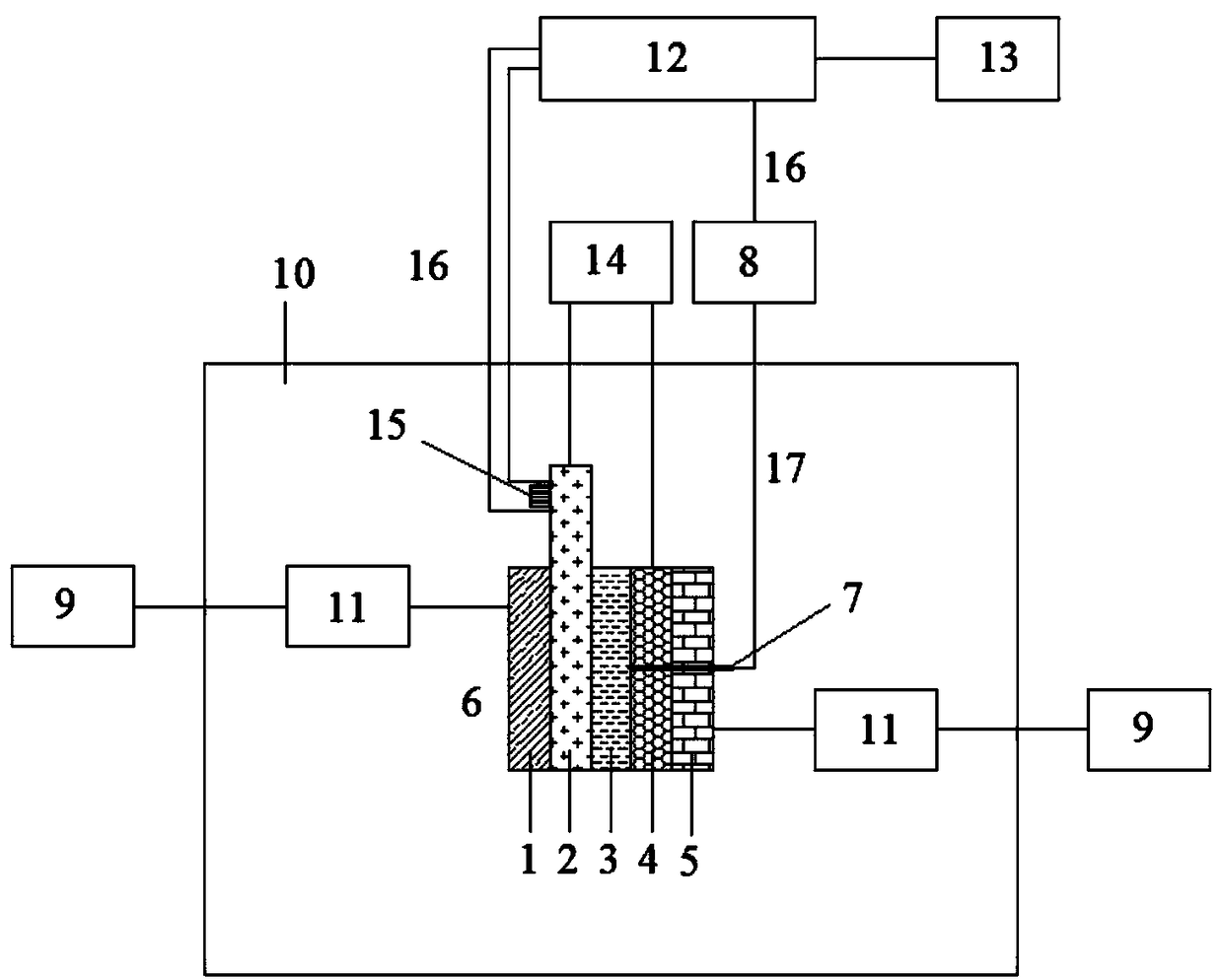
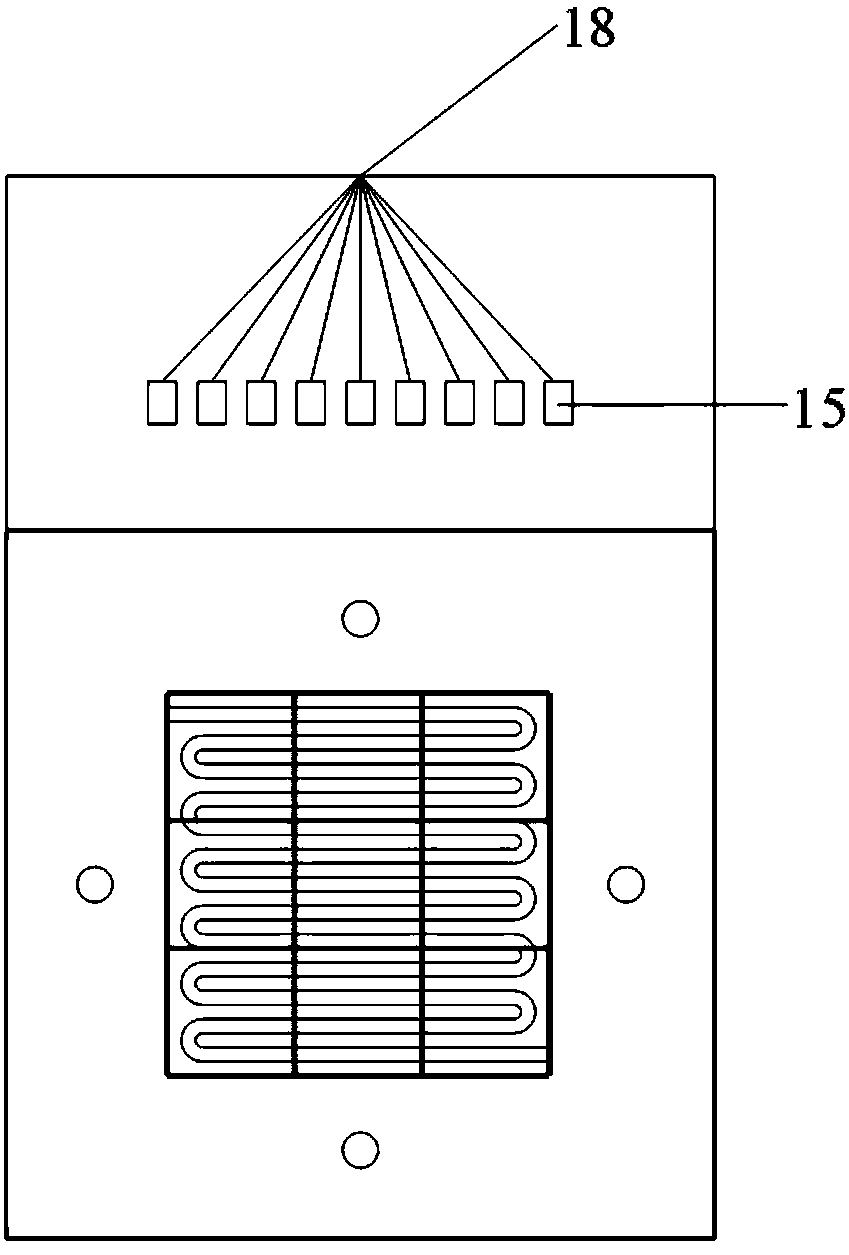
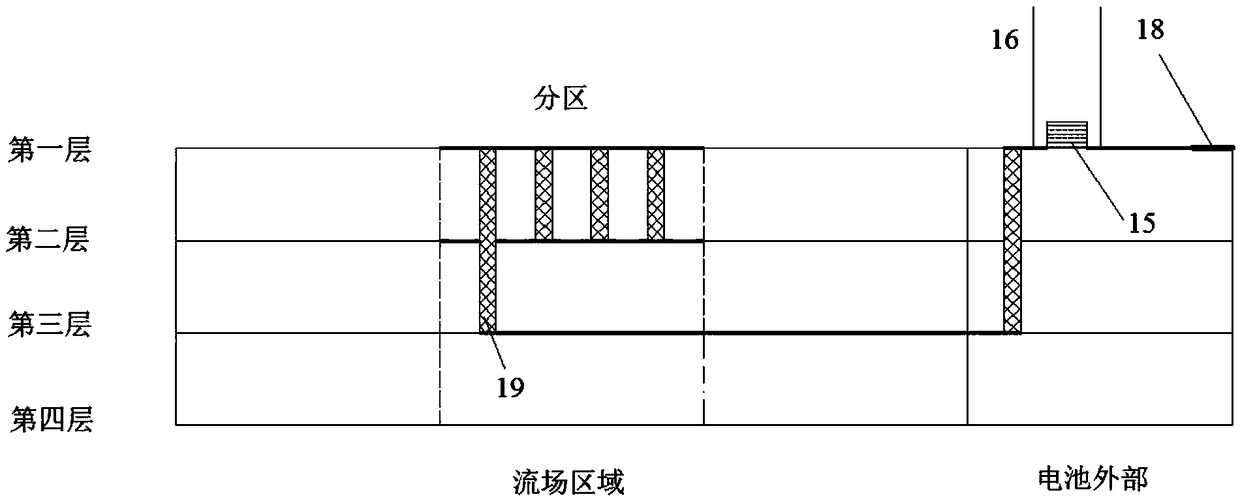
[0033] Such as figure 1 As shown, a fuel cell cold start current density and temperature zone test system, the fuel cell 6 includes an anode end plate 1, a current density test plate 2, a membrane electrode assembly 3, a cathode flow field plate 4, a cathode end plate 5. The current density test plate 2 is placed on the anode of the battery, and assembled into a fuel cell in the order of the anode end plate 1, the current density test plate 2, the membrane electrode assembly 3, the cathode flow field plate 4, and the cathode end plate 5 6. Both the cathode flow field plate 4 and the cathode end plate 5 have sockets, and the test system includes a fuel cell 6, a thermocouple 7, an ice bath 8, an air intake system module 9, and a high and low temperature cooling box 10. Cooling pipe 11, data acquisition...


PUM

PropertyMeasurementUnit
electrical resistanceaaaaaaaaaa

Abstract

The invention discloses a partition test system of the cold start current density and temperature of a fuel cell. A fuel cell system comprises a fuel cell, a thermocouple, an ice bath, an air intake system module, a high and low temperature alternating box, a cooling tube, a data acquisition module, a data processing module, and a load. The test method comprises the steps that: a current density test board is placed at an anode; both the cathode flow field plate and the cathode end plate have jacks, and the thermocouple is placed in the jack; the ice bath provides cold junction compensation for the thermocouple; the temperature in the high and low temperature alternating box is set to be the ambient temperature of the cold start; the intake system module supplies the fuel cell with oxidantand fuel and is connected to the load to make it work normally; the data acquisition module collects the voltage of the sampling resistor and the thermoelectric potential of the thermocouple. The data processing module converts the collected signal into a current density distribution map and a temperature distribution map at each moment of the fuel cell. Compared with the prior art, the inventionhas the advantages of low manufacturing cost, accurate measurement, simple structure and the like.

Description

technical field [0001] The invention belongs to the field of fuel cells, and in particular relates to a partition test system and method for the cold start current density and temperature of a fuel cell. Background technique [0002] Energy is the material basis for human survival, and it is also the source of power for economic growth. At present, most of people's utilization of coal, oil, natural gas and other energy sources have problems such as low utilization rate and environmental pollution. In order to adapt to the rapid development of society and economy, developing clean and sustainable energy and improving energy utilization efficiency have become urgent problems in today's society. Because the fuel cell itself has the advantages of no pollution to the environment, high energy conversion rate, and high reliability, it has broad development prospects in the new energy automobile industry, mobile power supply, and small and medium-sized power stations. Although the...

Claims


Application Information

Patent Timeline
Patent Type & Authority Applications(China)
IPC IPC(8): G01R19/08G01K7/12
CPCG01R19/08G01K7/12
Inventor 詹志刚袁冲姜攀星杨华赵桦粮潘牧
Owner WUHAN UNIV OF TECH
Learn More