An automatic floating and sinking submersible mixer

A submersible mixer, automatic technology, applied in the direction of mixer accessories, mixers, dissolving, etc., can solve the problems of limited working range, limited working range, troublesome installation, etc., to achieve efficient and fast work, ensure feasibility, and simple structure Effect

Active Publication Date: 2019-12-31
浙江星控信息技术有限公司
View PDF6 Cites 0 Cited by
  • Summary
  • Abstract
  • Description
  • Claims
  • Application Information

AI Technical Summary

Problems solved by technology

[0004] 1. The installation form of the existing submersible mixer must be supported by a fixed platform or a hard foundation, and the installation is more troublesome.
[0005] 2. The working range of the existing submersible mixer is completely limited by the guide rod, the working range is very limited and the working range of the mixer needs to be controlled artificially
[0006] At present, the relevant declared patents are: buoy type submersible mixer, application number CN201710612014. This patent mainly replaces the fixed platform support by adding a buoy bound to the mixer. Although it avoids the trouble of installation, it cannot realize the mixer in the vertical direction. The movement of the mixer is relatively limited, and the movement of the mixer in the pool in this patent still requires a traction rope to control the movement of the buoy, which cannot achieve efficient and fast work of the mixer; a submersible hyperboloid mixer, CN201410223998, also uses a buoy It replaces the platform, but the buoy relies on the external trachea water pipe to control the diving depth. Such a mixer needs manual control when working, and cannot realize the efficient and fast work of the mixer.

Method used


Image

  • An automatic floating and sinking submersible mixer
  • An automatic floating and sinking submersible mixer
  • An automatic floating and sinking submersible mixer

Examples


Embodiment Construction

[0028] The following will clearly and completely describe the technical solutions in the embodiments of the present invention with reference to the drawings in the embodiments of the present invention.

[0029] In describing the present invention, it is to be understood that the terms "radius", "upper", "lower", "left", "right", "top", "bottom", "inner", "outer" etc. indicate The orientation or positional relationship is based on the orientation or positional relationship shown in the drawings, and is only for the convenience of describing the present invention and simplifying the description, rather than indicating or implying that the referred device or element must have a specific orientation or be configured in a specific orientation. and operation, and therefore should not be construed as limiting the invention.

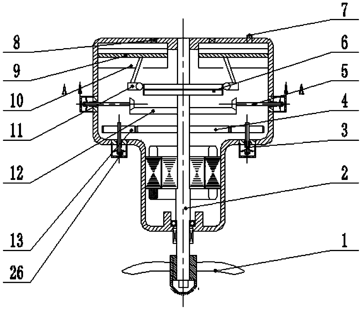
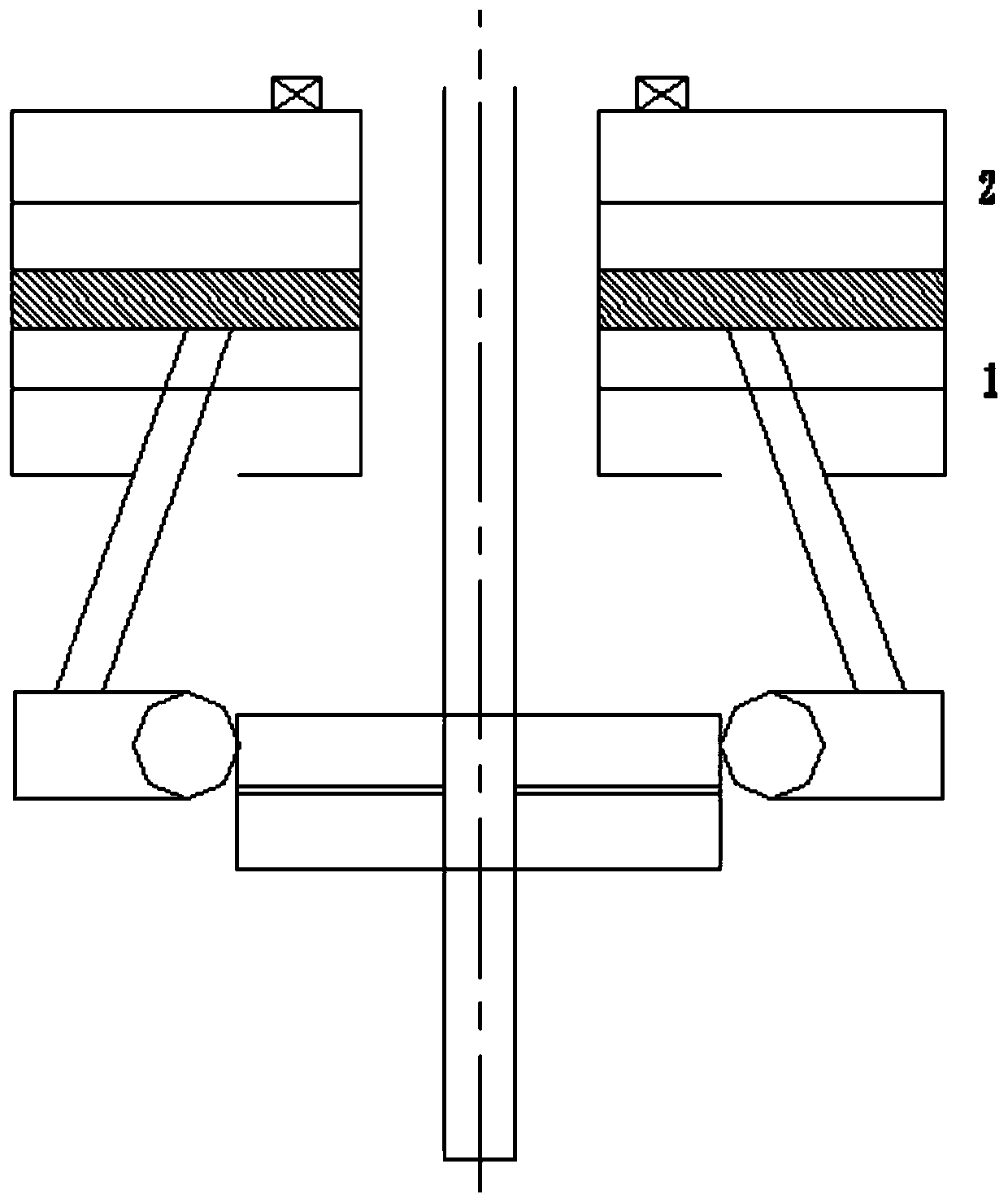
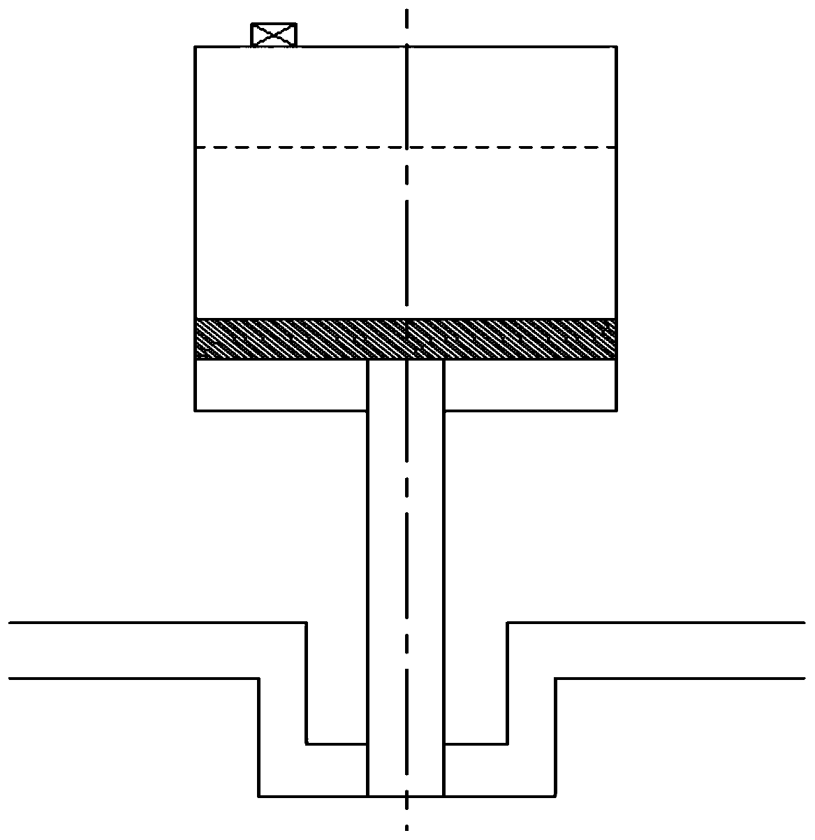
[0030] Depend on Figure 1 to Figure 5 As shown, an automatic floating submersible mixer includes a power part, a propulsion device part, and a buoyancy device...


PUM


Abstract

The invention discloses an automatic floating submersible mixer, which includes a power part, a propulsion device part and a buoyancy device part; the power part includes a submersible motor together with a motor shaft, and the propulsion device part includes gears one, two and three, a propulsion device, and a helical bevel gear Mechanism, buoyancy device includes electromagnetic clutch, connecting rod, piston, cavity. The power is transmitted to the propulsion device through gear meshing, the electromagnetic clutch is connected to the piston in the cavity through the connecting rod, the power is transmitted to the electromagnetic clutch through the motor shaft, and then to the connecting rod to control the reciprocating movement of the piston in the cavity; When the submersible mixer is working, the liquid in the cavity is sucked and discharged through the reciprocating movement of the piston, which changes the buoyancy and achieves the effect of controlling the rise and dive of the submersible mixer. At the same time, the propulsion device can provide power to make it stir in the horizontal position work, the present invention avoids the installation of fixed brackets and working platforms, and does not require human control at the same time, realizing efficient and quick work of the submersible mixer.

Description

technical field [0001] The present invention relates, in particular, to a sewage treatment equipment, especially to an automatic floating submersible mixer. Background technique [0002] Submersible mixer, also known as submersible propeller, is suitable for propulsion and agitation of sewage containing suspended solids, thin mud, industrial process liquid, etc. in the process of sewage treatment plants. The main functions of the submersible mixer are stirring, pushing, suspending, homogenizing, and preventing sludge and dirt from settling. It stirs the liquid through the rotation of the impeller driven by the motor to fully mix the liquid medium, and creates a water flow to strengthen the stirring, acting on the sewage, and the axial thrust generated makes the sludge water evenly mixed and prevents sludge from settling. The working environment of the submersible mixer is usually a sewage treatment tank. In order to prevent sludge from settling, the mixer needs to be kept f...

Claims


Application Information

Patent Timeline
Patent Type & Authority Patents(China)
IPC IPC(8): B01F13/00B01F15/00
CPCB01F33/503B01F35/3204B01F2101/305
Inventor 刘栋孙思亮张亚玲任霞光
Owner 浙江星控信息技术有限公司
Why Eureka
Try Eureka