Pile foundation punching device and method

A technology for pile foundations and holes to be opened, applied in drilling equipment and methods, earthwork drilling, construction, etc., can solve the problems of difficult to guarantee construction progress, limited opening depth, slow opening speed, etc., and achieve easy construction. and field operation, long service life and short forming time

Pending Publication Date: 2018-09-25
HUAZHONG UNIV OF SCI & TECH
View PDF8 Cites 2 Cited by
  • Summary
  • Abstract
  • Description
  • Claims
  • Application Information

AI Technical Summary

Problems solved by technology

[0003] Aiming at the above defects or improvement needs of the prior art, the present invention provides a pile foundation hole opening device and method, thereby solving the problems of slow hole opening speed, long construction period, limited hole depth and Technical problems such as difficulty in guaranteeing construction progress

Method used


Image

  • Pile foundation punching device and method
  • Pile foundation punching device and method
  • Pile foundation punching device and method

Examples


Embodiment 1

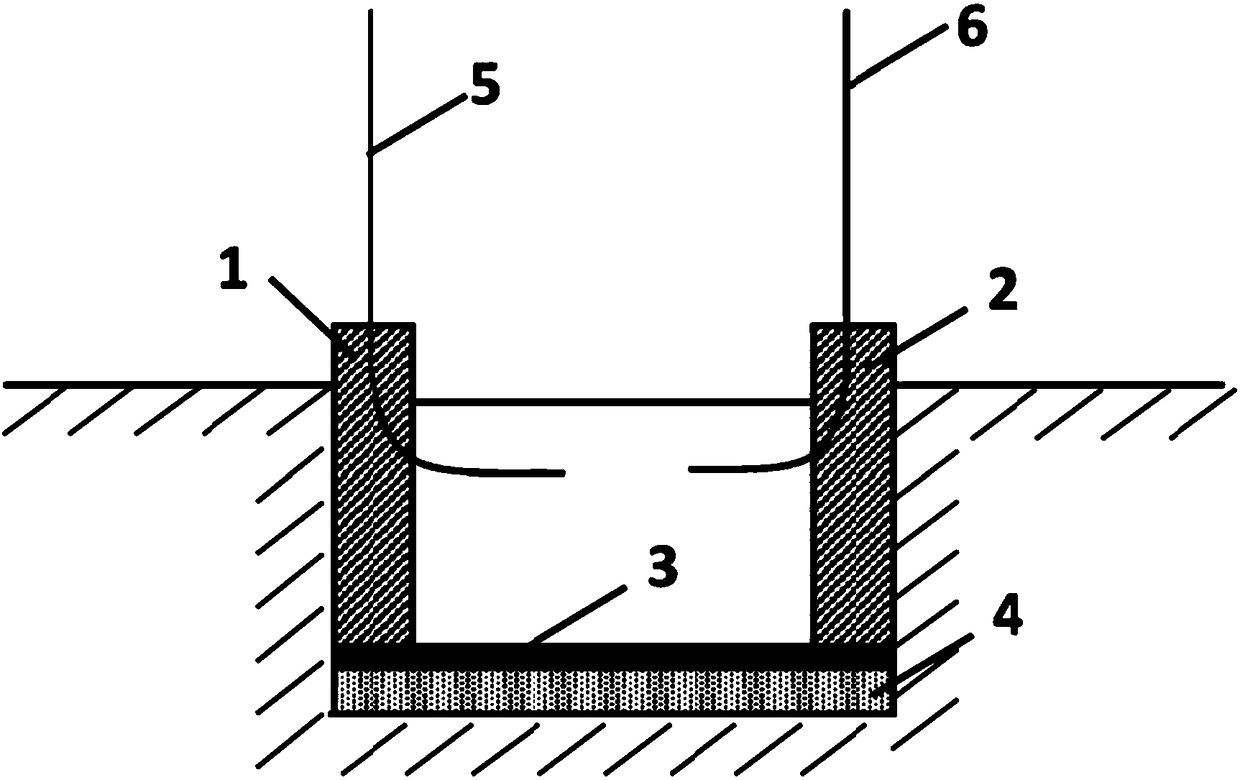
[0034] Such as figure 1 As shown, the overall structure of the cast-in-situ pile hole-forming device according to the embodiment of the present invention includes: a high-voltage electrode 1 , a ground electrode 2 , an aluminum wire 3 , a soil layer 4 , a water inlet pipe 5 , and a water outlet pipe 6 .

[0035] The aluminum wire 3 is arranged on the surface of the soil layer 4, and its two ends are respectively connected with the high voltage electrode 1 and the ground electrode 2. Water is filled between the high voltage electrode 1 and the ground electrode 2.

[0036] The hole forming method comprises the following steps:

[0037] (1) The aluminum wire 3 is placed close to the soil layer 4, arranged in parallel on the surface of the soil layer 4 along strips, and the two ends of the aluminum wire 3 are respectively connected to the high voltage electrode 1 and the ground electrode 3;

[0038] (2) Through the water inlet pipe 5, water is introduced between the high-voltage...

Embodiment 2

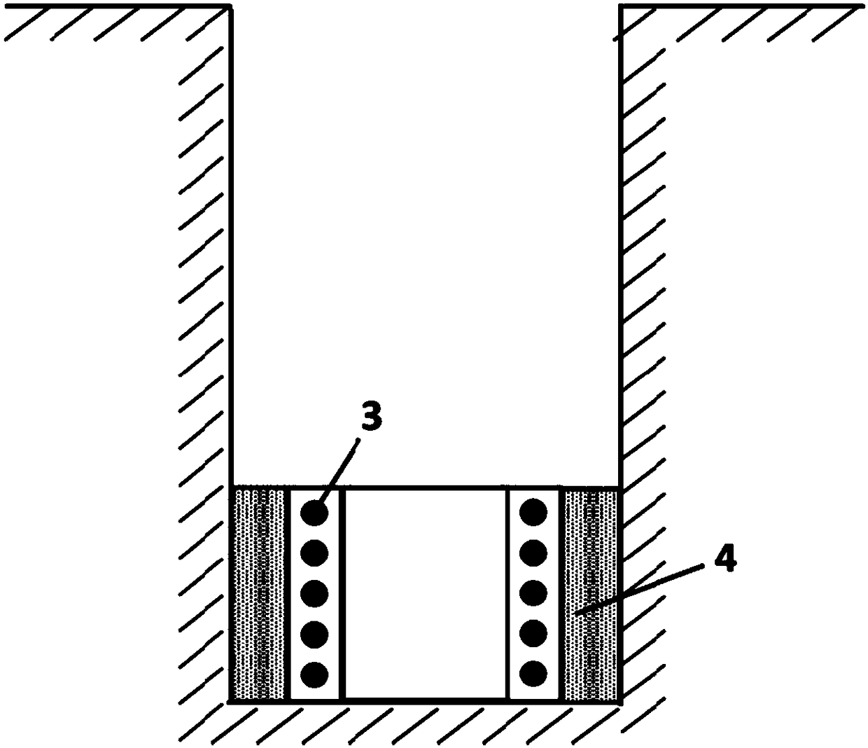
[0046] Such as figure 2 As shown, the overall structure of the reaming device according to the embodiment of the present invention includes: a coil 3 and a soil layer 4 .

[0047] The hole reaming method includes the following steps:

[0048](1) The coil 3 is placed in the water tank and placed close to the soil layer 4, and the water tank is filled with water;

[0049] (2) The coil 3 is energized. Since the coil 3 is made of aluminum material, the Joule heating effect is significant under high current, energy accumulates in the coil, the aluminum wire is gasified at high temperature, and an explosion occurs to generate a huge shock wave. At the same time, after the gasification of the aluminum , The contact surface with water is greatly increased, and the chemical reaction between aluminum and water produces hydrogen, which releases huge energy and further increases the impact force. The superposition of these two forces causes the extrusion and crushing of the soil layer ...


PUM


Abstract

The invention discloses a pile foundation punching device and method. The device comprises a punching force generating mechanism; the punching force generating mechanism comprises a metal channel and / or a liquid channel; the punching force generating mechanism is used to utilize a first impact force generated by a gasification explosion of an electrified mental in the metal channel, a second impact force generated by discharging on a liquid in the liquid channel by a power source, or a third impact force generated by the gasification explosion of the metal in the metal channel and a reaction between the mental and the liquid in the liquid channel as driving forces for punching; the driving forces cause the extrusion and crushing of a soil layer to be punched, so as to achieve a punching effect. The device can be used for forming holes and reaming holes of a pile foundation, can improve the working efficiency of pouring piles, and is simple in structure, convenient to operate, small inenergy consumption, safe, reliable and pollution-free; at the same time, the impact forces can be flexibly adjusted, and the device is suitable for different soils, especially suitable for forming holes and reaming holes in sand-gravel layers, hard soil layers, hard rock layers containing boulders and soil layers containing groundwater.

Description

technical field [0001] The invention belongs to the field of pile foundation construction, and more specifically relates to a pile foundation opening device and method. Background technique [0002] The cast-in-situ pile is a pile-forming process that directly opens a hole on the designed pile position, adds a reinforcement cage in the hole after the hole is formed, and then pours concrete. Common pile forming methods include percussion drilling and manual digging. Percussion drilling usually uses percussion drilling rig or winch to raise the percussion drill bit with drill blade and high quality, and cuts the rock layer or squeezes the soil layer by the impact force of free fall, and then uses a special slag removal tool to dig out the soil and form a hole. The equipment is simple and easy to operate, but the hole forming speed is slow, the construction period is long, the drill bit is easy to wear, and accidents such as hole deviation, drill sticking and drill drop are pr...

Claims


Application Information

Patent Timeline
IPC IPC(8): E21B1/00E21B7/00E21B7/28
CPCE21B1/02E21B7/00E21B7/28
Inventor 李亮黄玉杰韩小涛
Owner HUAZHONG UNIV OF SCI & TECH
Why Eureka
Try Eureka