
Laser welding and testing integrated method for condensation pipe

A technology of laser welding and condensation pipes, which is applied in the direction of laser welding equipment, welding equipment, metal processing equipment, etc., can solve the problems that the online automatic test of weld quality has not been realized, it is difficult to realize the automation of welding process, and it is difficult to ensure the sealing of condensation pipes, etc. , to achieve the effect of realizing online testing, reducing temperature inhomogeneity and ensuring metallurgical effect

Active Publication Date: 2018-09-28
常州市托耐多焊割科技有限公司
View PDF5 Cites 1 Cited by
  • Summary
  • Abstract
  • Description
  • Claims
  • Application Information

AI Technical Summary

Problems solved by technology

[0004] According to the principle and production method of the evaporator, the shape of the ice cubes made by the ice maker is also different; the condenser tube is one of the indispensable accessories in the application process of the evaporator; the condenser tube is mainly composed of a column tube, a U-shaped tube and Composed of spacers, the three need to be fixed together by welding; the traditional welding method is mainly flame spray welding, which needs to continuously swing and rotate the workpiece or move the flame around the workpiece during the welding process to maintain the joint surface The temperature is consistent and reaches the welding temperature; due to the low accuracy of the welding position of the flame spray welding, the weld seam is wide, prone to defects such as pores and micro cracks, and the strength of the weld seam is not high, so it is difficult to ensure the sealing of the condensation pipe under long-term pressure work In addition, the welding process is difficult to operate, and it is difficult to realize the automation of the welding process, and the online automatic test of the follow-up weld quality has not yet been realized.

Method used


Image

  • Laser welding and testing integrated method for condensation pipe
  • Laser welding and testing integrated method for condensation pipe
  • Laser welding and testing integrated method for condensation pipe

Examples


Embodiment Construction

[0038] Below in conjunction with accompanying drawing and specific embodiment the present invention is described in further detail;

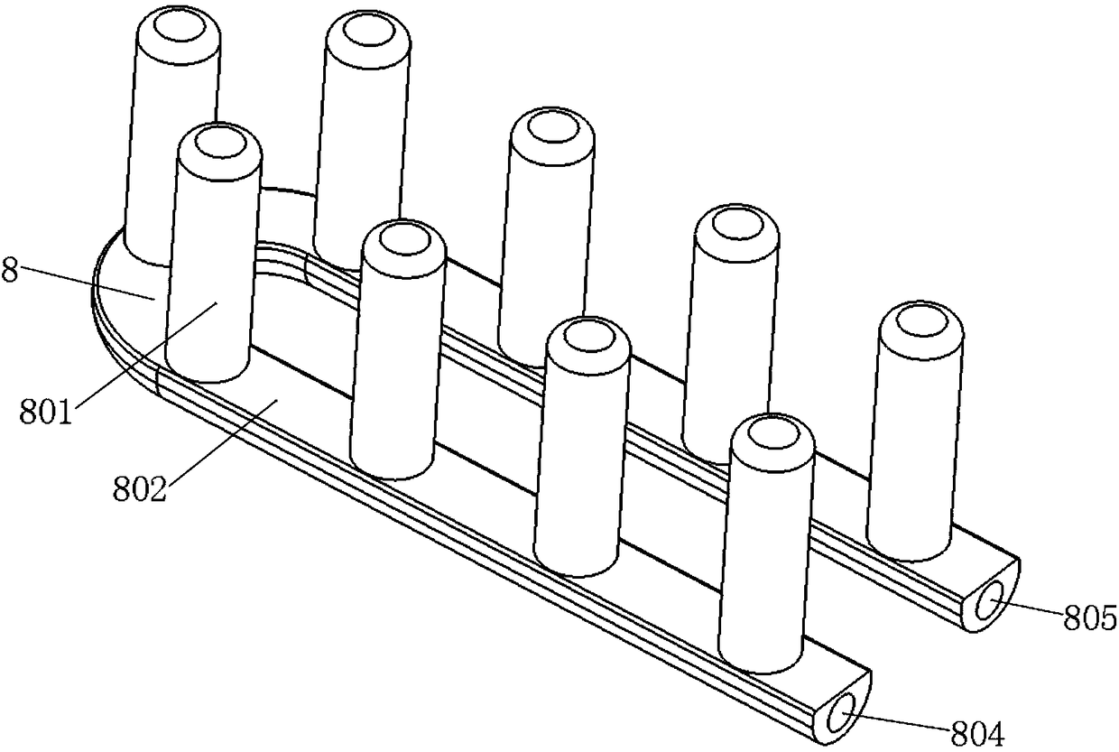
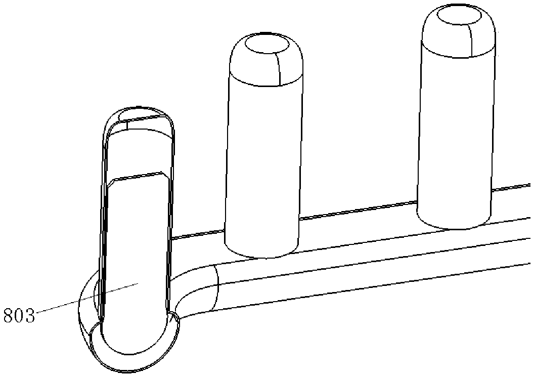
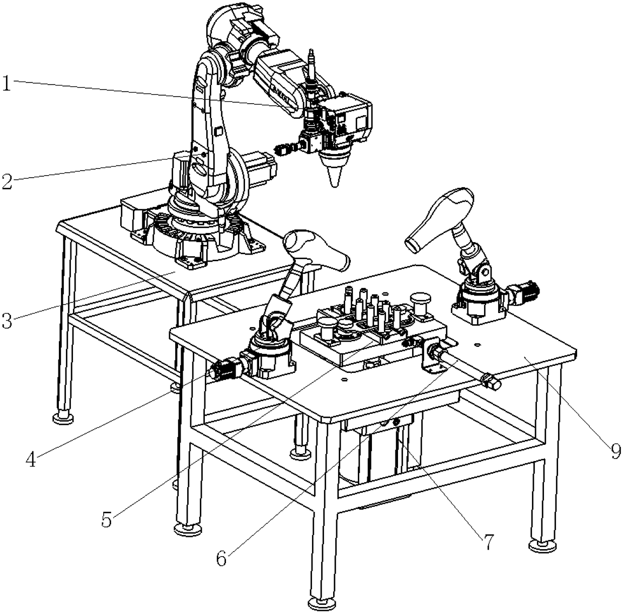
[0039] Such as Figure 1-13 As shown, the condenser tube 8 of the present invention is composed of a U-shaped tube 802 and a plurality of column tubes 801; the column tube 801 is a cylindrical structure with a hollow inside, one end closed, and the other end open, and the wall thickness of the cylinder is 0.2 mm ~ 2mm, a separator 803 is arranged in the middle of the column tube 801, thereby dividing the internal space of the column tube 801 into two parts; mm~0.05mm, that is, when the length direction of the separator 803 is assembled along the axial direction of the column tube 801 (that is, the width direction of the separator 803 is parallel to the radial direction of the column tube 801), the two sides of the length direction are aligned with the column tube 801 The wall of the tube is a tight interference fit; there is a gap for gas or li...


PUM

PropertyMeasurementUnit
thicknessaaaaaaaaaa

Abstract

The invention provides a laser welding and testing integrated method for a condensation pipe. The method comprises the steps that a welded condensation pipe workpiece is assembled and is clamped and fixed, a U-shaped pipe is inflated with protective gas, and a laser machining head is moved to the joint position; a welding laser beam is output, a multi-freedom-degree mechanical arm is used for controlling the movement of the laser machining head, a focusing laser beam conducts one-circle scanning along the stand column pipe installing hole outline position, and an integral annular welding lineis formed; in the scanning process, the laser power is adjusted in real time, and a laser ring welding line is obtained; through an automatic lifting device, the condensation pipe workpiece obtained after welding is immersed in water, air tightness of the condensation pipe workpiece under the standard testing air pressure is tested, and when points of solder skips are found, welding is conducted again; or otherwise, hot air is adopted for blowing-dry after automatic elevating. According to the laser welding and testing integrated method for the condensation pipe, integrated and automatic laserwelding and testing and online welding defect repairing of the U-shaped condensation pipe are achieved, and the technical problems about automatic welding and online automatic welding line quality testing of the kind of components for a long term are solved.

Description

technical field [0001] The invention belongs to the field of laser processing, and in particular relates to an integrated method for laser welding and testing of condenser tubes. Background technique [0002] At present, ice cubes are widely used in aquatic products, food, supermarkets, dairy products, medicine, chemistry, vegetable preservation and transportation, marine fishing and other industries. With the development of society and the continuous improvement of people's production levels, more and more industries use ice. The quality requirements for ice are getting higher and higher, and the requirements for high performance, low failure rate and hygiene of ice making equipment are becoming more and more urgent. [0003] The ice machine is a mechanical device that passes water through the evaporator and is cooled by the refrigeration system to make ice; the refrigeration system of the ice machine is composed of a compressor, a condenser, a dry filter, an expansion valv...

Claims


Application Information

Patent Timeline
Patent Type & Authority Applications(China)
IPC IPC(8): B23K26/24B23K26/14B23K26/70
CPCB23K26/14B23K26/24B23K26/70B23K26/702
Inventor 魏鑫磊
Owner 常州市托耐多焊割科技有限公司
Learn More