Refrigeration house refrigerating system

A technology of refrigeration system and cold storage, applied in refrigerators, refrigeration components, refrigeration and liquefaction, etc., can solve the problems of difficult automation, low refrigeration efficiency, difficult oil return, etc., achieve efficient automatic control, improve cold storage capacity, and improve storage temperature. slow effect

Pending Publication Date: 2018-09-28
北京中冷高科制冷设备有限公司
View PDF7 Cites 1 Cited by
  • Summary
  • Abstract
  • Description
  • Claims
  • Application Information

AI Technical Summary

Problems solved by technology

[0003] A liquid ammonia refrigeration system is generally composed of a refrigeration unit, an ammonia oil separator, a high-pressure liquid receiver, a condenser, a low-pressure circulating liquid storage tank, an oil collector, an ammonia pump, and a cooling fan. The cost is low, but this kind of system has complex pipelines, difficult operation and management, and requires high professional level of operators. At the same time, because it is difficult to realize automation, the system requires operators to be on duty 24 hours a day for operation and management
In addition, there are problems such as difficult oil return and easy leakage of liquid ammonia in the direct evaporation system. Once ammonia gas leaks, it is very easy to cause an explosion accident
[0004] The investment cost of the fluorine refrigeration system is high in the initial stage of construction, and as a direct evaporation system, the freon needs to be mixed with lubricating oil. When the vertical height or the total length of the copper pipe connected to the outdoor unit of the refrigeration system increases, it will cause serious oil return in the refrigeration system. smooth, resulting in a significant reduction in cooling efficiency and a substantial increase in power consumption
Moreover, Freon refrigerants have no obvious characteristics when they leak, so the operating costs will be greatly increased in leak repair and refrigerant filling

Method used


Image

  • Refrigeration house refrigerating system
  • Refrigeration house refrigerating system
  • Refrigeration house refrigerating system

Examples


Embodiment Construction

[0035] In order to make the object, technical solution and advantages of the present invention clearer, the present invention will be further described in detail below in conjunction with the accompanying drawings.

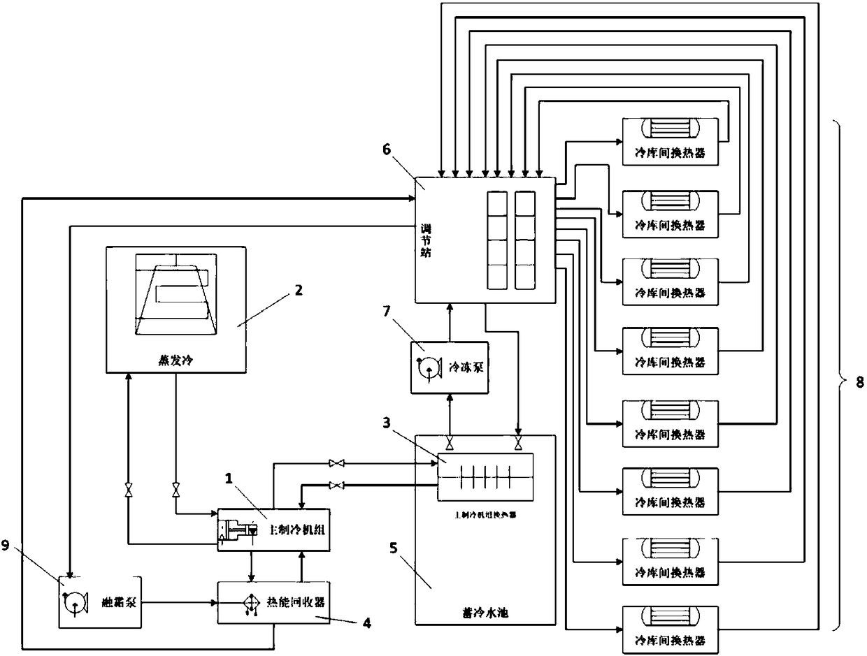
[0036] figure 1 is a schematic diagram of the system structure according to an embodiment of the present invention. Combine below figure 1 This embodiment will be described.

[0037] The cold storage refrigeration system of this embodiment includes a first refrigeration cycle system and a second refrigeration cycle system, the first refrigeration cycle system includes a main refrigeration unit 1, an evaporative condenser 2 and a main refrigeration unit heat exchanger 3, and the second The refrigerating cycle system includes a cold storage pool 5 , a regulating station 6 , a refrigeration pump 7 and a heat exchanger 8 between cold stores. The main refrigerating unit 1 described in this embodiment uses a semi-hermetic screw compressor, with a storage capacity of ...


PUM


Abstract

The invention discloses a refrigeration house refrigerating system which comprises a first refrigerating circulating system and a second refrigerating circulating system, wherein the first refrigerating circulating system comprises a main refrigerating unit, an evaporative condenser and a main refrigerating unit heat exchanger; the second refrigerating circulating system comprises a cold accumulation water tank, a refrigerating pump, an adjusting station and heat exchangers between refrigeration houses; the cold accumulation water tank, the refrigerating pump, the adjusting station, the heat exchangers between refrigeration houses and connected pipelines are filled with intercooling liquid, wherein the intercooling liquid is potassium formate-pentaerythritol-water dispersible polyisocyanates-water system secondary refrigerant; and the main refrigerating unit heat exchanger of the first refrigerating circulating system is completely immersed in the intercooling liquid in the cold accumulation water tank of the second refrigerating circulating system.

Description

technical field [0001] The invention relates to the technical field of low-temperature refrigeration, in particular to a refrigerator refrigeration system. Background technique [0002] At present, food safety and cold chain construction have entered a period of rapid development. As the central link of low-temperature food circulation, cold storage is crucial to all links of the entire cold chain. For the prior art of large-scale cold storage, liquid ammonia and freon are mainly used as refrigerants for refrigeration. [0003] A liquid ammonia refrigeration system is generally composed of a refrigeration unit, an ammonia oil separator, a high-pressure liquid receiver, a condenser, a low-pressure circulating liquid storage tank, an oil collector, an ammonia pump, and a cooling fan. The cost is low, but this kind of system has complex pipelines, difficult operation and management, and requires high professional level of operators. At the same time, because it is difficult to...

Claims


Application Information

Patent Timeline
Patent Type & Authority Applications(China)
IPC IPC(8): F25D13/00F25D29/00F25B41/06F25B47/02F25B1/047F25B41/31
CPCF25B1/047F25B47/022F25D13/00F25D29/005F25B41/31
Inventor 李梅
Owner 北京中冷高科制冷设备有限公司
Why Eureka
Try Eureka