Fuel oil rubber tube and preparation method thereof
A rubber tube and fuel technology, applied in rubber layered products, chemical instruments and methods, hoses, etc., can solve problems such as high temperature resistance and low permeability, and achieve wear resistance, corrosion resistance, impact resistance, high production efficiency, and good production efficiency. The effect of oil resistance
- Summary
- Abstract
- Description
- Claims
- Application Information
AI Technical Summary
Problems solved by technology
Method used
Image

Examples
Embodiment 1
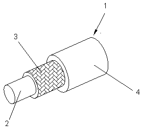
[0054] The fuel rubber hose of this embodiment includes a rubber hose body 1, the rubber hose body 1 sequentially includes an inner rubber layer 2, a reinforced fabric layer 3 and an outer rubber layer 4 from the inside to the outside, and the reinforced fabric layer 3 includes The parallel reinforcement yarns arranged longitudinally in the fabric and the yarns vertically intersecting with the reinforcement yarns, the inner rubber layer 2 is an inner rubber layer of hydrogenated nitrile rubber, and the outer rubber layer 4 is an outer rubber layer of EPDM rubber.
[0055] Wherein, the reinforcing yarns in the reinforcing fabric layer 3 are selected from aramid fibers, and the yarns vertically intersecting with the reinforcing yarns are selected from polyester fibers.
[0056] Wherein, the reinforcing fabric layer 3 is formed by the reinforcing yarn and the yarn through weaving or winding process.
[0057] Wherein, the surface of the reinforcing fabric layer 3 is coated with an...
Embodiment 2
[0089] The fuel rubber hose of this embodiment includes a rubber hose body 1, the rubber hose body 1 sequentially includes an inner rubber layer 2, a reinforced fabric layer 3 and an outer rubber layer 4 from the inside to the outside, and the reinforced fabric layer 3 includes The parallel reinforcement yarns arranged longitudinally in the fabric and the yarns vertically intersecting with the reinforcement yarns, the inner rubber layer 2 is an inner rubber layer of hydrogenated nitrile rubber, and the outer rubber layer 4 is an outer rubber layer of EPDM rubber.
[0090] Wherein, the reinforcing yarns in the reinforcing fabric layer 3 are selected from aramid fibers, and the yarns vertically intersecting with the reinforcing yarns are selected from polyester fibers.
[0091] Wherein, the reinforcing fabric layer 3 is formed by the reinforcing yarn and the yarn through weaving or winding process.
[0092] Wherein, the surface of the reinforcing fabric layer 3 is coated with an...
Embodiment 3
[0124] The fuel rubber hose of this embodiment includes a rubber hose body 1, the rubber hose body 1 sequentially includes an inner rubber layer 2, a reinforced fabric layer 3 and an outer rubber layer 4 from the inside to the outside, and the reinforced fabric layer 3 includes The parallel reinforcement yarns arranged longitudinally in the fabric and the yarns vertically intersecting with the reinforcement yarns, the inner rubber layer 2 is an inner rubber layer of hydrogenated nitrile rubber, and the outer rubber layer 4 is an outer rubber layer of EPDM rubber.
[0125] Wherein, the reinforcing yarns in the reinforcing fabric layer 3 are selected from aramid fibers, and the yarns vertically intersecting with the reinforcing yarns are selected from polyester fibers.
[0126] Wherein, the reinforcing fabric layer 3 is formed by the reinforcing yarn and the yarn through weaving or winding process.
[0127] Wherein, the surface of the reinforcing fabric layer 3 is coated with an...
PUM
 Abstract
Description
Claims
Application Information
 - R&D
- Intellectual Property
- Life Sciences
- Materials
- Tech Scout
- Unparalleled Data Quality
- Higher Quality Content
- 60% Fewer Hallucinations
Browse by: Latest US Patents, China's latest patents, Technical Efficacy Thesaurus, Application Domain, Technology Topic, Popular Technical Reports.
© 2025 PatSnap. All rights reserved.Legal|Privacy policy|Modern Slavery Act Transparency Statement|Sitemap|About US| Contact US: help@patsnap.com