Supercharge Your Innovation With Domain-Expert AI Agents!

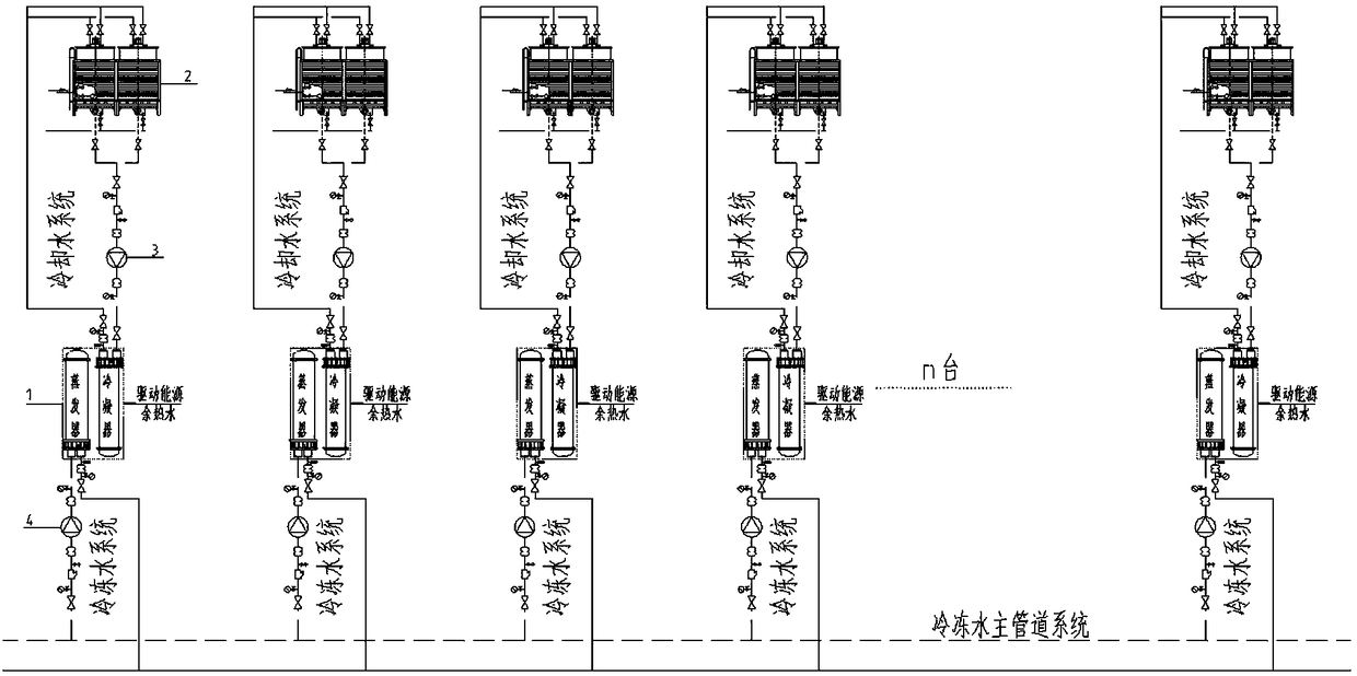
Large industrial waste heat refrigeration system and method

A waste heat refrigeration, large-scale industrial technology, used in household refrigeration devices, lighting and heating equipment, machines using waste heat, etc. The effect of investment and operation energy consumption, reduction of transmission energy consumption, and reduction of motor power

Pending Publication Date: 2018-10-02
山东华创能源设备有限公司
View PDF2 Cites 0 Cited by
  • Summary
  • Abstract
  • Description
  • Claims
  • Application Information

AI Technical Summary

Problems solved by technology

[0003] However, the existing waste heat refrigeration system, cooling water, and chilled water systems are all designed in the form of a combination of centralized water pumps, which results in a significant increase in energy consumption for transportation
At the same time, for large-scale equipment, since there are many refrigeration equipment, generally more than ten sets, the combination of centralized water pumps will also increase the floor area of ​​the machine room and complicate the power distribution system.
However, the large area of ​​the machine room will increase the construction cost of the plant or machine room, which sometimes outweighs the gain for the application of waste heat refrigeration technology; the complexity of the power distribution system often leads to increased motor power, interference between power equipment, and transmission High energy consumption, and the control process of the load change of each equipment is complicated, and the control accuracy or effect is not good.

Method used


Image

  • Large industrial waste heat refrigeration system and method

Examples


Embodiment Construction

[0028] The present invention will be further described below in conjunction with the accompanying drawings and embodiments.

[0029] It should be pointed out that the following detailed description is exemplary and intended to provide further explanation to the present application. Unless defined otherwise, all technical and scientific terms used herein have the same meaning as commonly understood by one of ordinary skill in the art to which this application belongs.

[0030] It should be noted that the terminology used here is only for describing specific implementations, and is not intended to limit the exemplary implementations according to the present application. As used herein, unless the context clearly dictates otherwise, the singular is intended to include the plural, and it should also be understood that when the terms "comprising" and / or "comprising" are used in this specification, they mean There are features, steps, operations, means, components and / or combinatio...


PUM


Abstract

The invention discloses a large industrial waste heat refrigeration system. The large industrial waste heat refrigeration system comprises multiple waste heat refrigeration units. Each waste heat refrigeration unit comprises a cooling tower, a cooling water system, a chilled water system, a waste heat absorption type water chilling unit, a cooling water circulating water pump, and a chilled watercirculating water pump. The waste heat absorption type water chilling water unit, the cooling water circulating water pump and the cooling water system of each waste heat refrigeration unit are connected to form a cooling water circulating subsystem. The waste heat refrigeration units are independent from one another, and each waste heat refrigeration unit works alone. According to one chilled water system, the corresponding waste heat absorption type water chilling unit, the corresponding chilled water circulating water pump and the chilled water system are connected in sequence to from a chilled water circulating subsystem. The waste heat refrigeration units not only are independent from one another and but also are connected with one another.

Description

technical field [0001] The invention relates to a large-scale industrial waste heat refrigeration system and method. Background technique [0002] With the country's increasing emphasis on environmental protection and energy conservation, the application of waste heat recovery and reuse technology has gradually spread. As the main means of utilization, waste heat refrigeration or waste heat recovery technology is valued by the industry. [0003] However, the existing waste heat refrigeration system, cooling water, and chilled water systems are all designed in the form of a combination of centralized water pumps, which results in a significant increase in energy consumption for transportation. At the same time, for large-scale equipment, since there are many refrigeration equipment, generally more than ten, the combination of centralized water pumps will also increase the floor area of ​​the machine room and complicate the power distribution system. However, the large area ...

Claims


Application Information

Patent Timeline
Patent Type & Authority Applications(China)
IPC IPC(8): F25B27/02F25D17/02
CPCF25B27/02F25D17/02
Inventor 焦保凯高朋郭延军赵宇王永正
Owner 山东华创能源设备有限公司
Features
  • R&D
  • Intellectual Property
  • Life Sciences
  • Materials
  • Tech Scout
  • Unparalleled Data Quality
  • Higher Quality Content
  • 60% Fewer Hallucinations
Learn More