
Electronic package and substrate construction thereof

一种电子封装件、电子元件的技术,应用在电气元件、电固体器件、电路等方向,能够解决封装基板18裂开、焊球12不沾锡、可靠度问题等问题,达到降低制程时间、降低制作成本、提升可靠度的效果

Inactive Publication Date: 2018-10-09
SILICONWARE PRECISION IND CO LTD
View PDF11 Cites 2 Cited by
  • Summary
  • Abstract
  • Description
  • Claims
  • Application Information

AI Technical Summary

Problems solved by technology

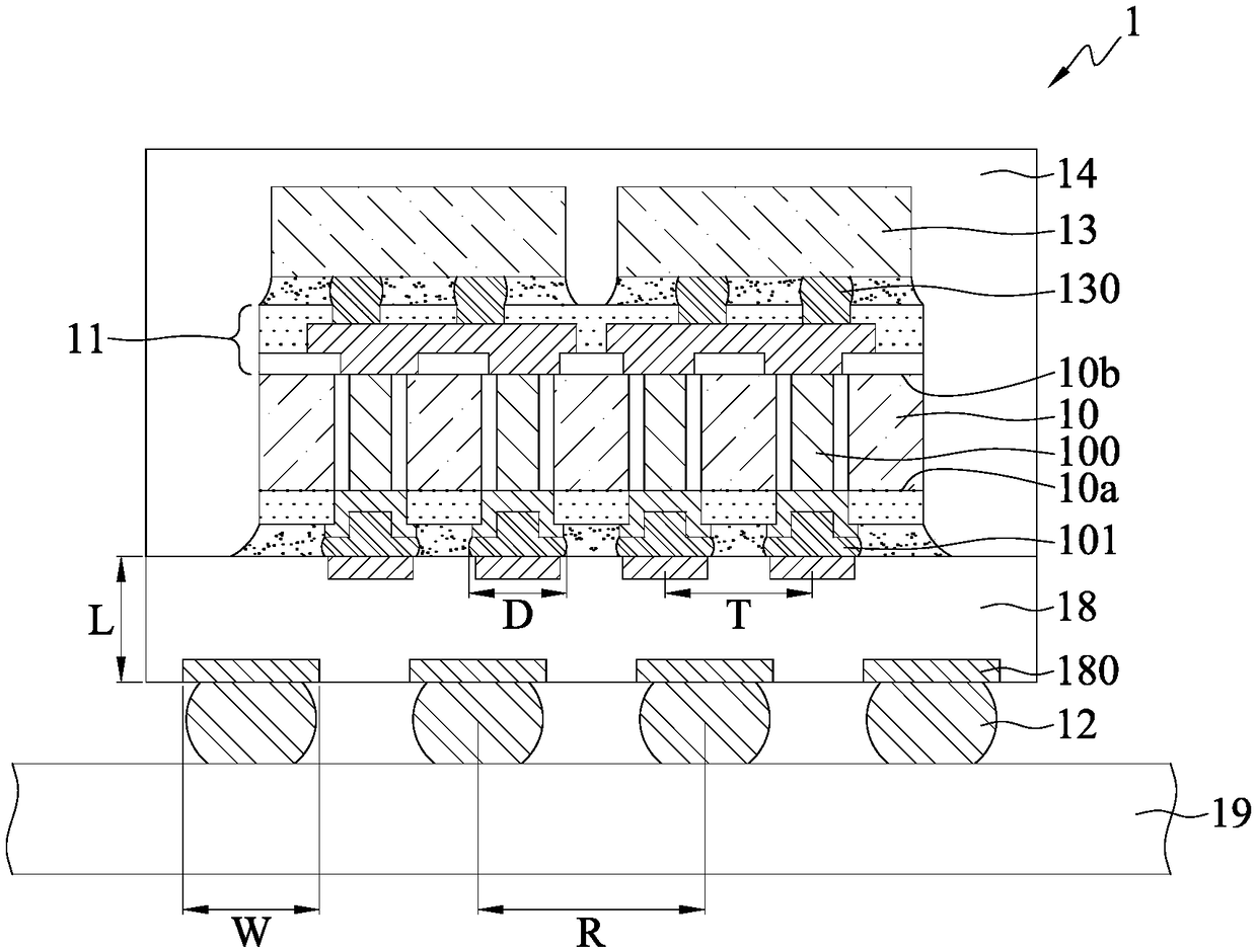
[0004] In the aforementioned semiconductor package 1, due to the miniaturization of the semiconductor chip 13 in response to the demand, the area of ​​the transfer side 10a (or the crystal placement side 10b) of the silicon interposer 10 is also getting smaller and smaller, and when the silicon interposer 10 If the surface of the transfer side 10a (or die placement side 10b) is extremely small, the packaging substrate 18 will affect the degree of warping of the semiconductor package 1
[0005] In detail, the packaging substrate 18 is made of organic material, so the coefficient of thermal expansion (CTE) of the packaging substrate 18 and the silicon interposer 10 does not match (mismatch), thus prone to uneven thermal stress, resulting in thermal cycle (thermal cycle) ) when the packaging substrate 18 is greatly warped (warpage), so that the ball planting condition is not good (that is, the solder ball 12 falls), the solder ball 12 does not stick to tin (non-wetting) or the packaging substrate 18 Reliability problems such as cracking, which in turn lead to reliability problems in terminal electronic products (such as computers, mobile phones, etc.) using the semiconductor package 1
[0006] In addition, the thickness L of the packaging substrate 18 is extremely thick (approximately 100 to 500 microns), so that the overall height of the existing semiconductor package 1 exceeds 1 mm (the thickness of the current package needs to be less than 1 mm), and the silicon The interposer 10 needs to be provided on the packaging substrate 18 through the conductive elements 101, which makes it difficult to reduce the overall thickness of the semiconductor package 1, making it difficult for electronic products using the semiconductor package 1 to meet the miniaturization requirements.

Method used


Image

  • Electronic package and substrate construction thereof
  • Electronic package and substrate construction thereof
  • Electronic package and substrate construction thereof

Examples


Embodiment Construction

[0062] The embodiments of the present invention are described below through specific specific examples, and those skilled in the art can easily understand other advantages and effects of the present invention from the contents disclosed in this specification.

[0063] It should be noted that the structures, proportions, sizes, etc. shown in the drawings in this specification are only used to cooperate with the contents disclosed in the specification for the understanding and reading of those skilled in the art, and are not used to limit the implementation of the present invention. Restricted conditions, it does not have technical substantive significance, any structural modification, proportional relationship change or size adjustment, without affecting the effect that the present invention can produce and the purpose that can be achieved, should still fall within the present invention. The disclosed technical content must be within the scope of coverage. Meanwhile, terms such...


PUM


Abstract

The invention provides an electronic package and a substrate construction thereof including a silicon substrate for carrying a chip on an upper side thereof, and a circuit structure formed underneaththe silicon substrate for being connected to solder balls via conductive pads of the circuit structure, thereby obtaining the same specification of the conductive pads as ball-planting pads of conventional package substrates and avoiding the manufacturing and use of conventional package substrates.

Description

technical field [0001] The invention relates to a semiconductor packaging process, in particular to an electronic package and its substrate structure. Background technique [0002] With the vigorous development of the electronic industry, electronic products are gradually moving towards the trend of multi-function and high performance. Technologies currently used in the field of chip packaging, such as Chip Scale Package (CSP for short), Direct Chip Attached (DCA for short) or Multi-Chip Module (MCM for short) ) and other flip-chip packaging modules, or integrate chips into three-dimensional integrated circuit (3D IC) chip stacking technology by three-dimensional stacking. [0003] figure 1 It is a schematic cross-sectional view of a conventional three-dimensional integrated circuit chip stacked semiconductor package 1 . Firstly, a through silicon interposer (TSI for short) 10 is provided with opposite transfer side 10a and die placement side 10b, and the silicon interpos...

Claims


Application Information

Patent Timeline
Patent Type & Authority Applications(China)
IPC IPC(8): H01L23/48H01L23/498
CPCH01L23/481H01L23/49822H01L23/147H01L23/3128H01L23/3135H01L23/49816H01L23/49827H01L2224/16225H01L2224/32225H01L2224/73204H01L2924/15311H01L2924/181H01L2924/18161H01L2924/00012H01L2924/00H01L23/14H01L23/28
Inventor 郑子企罗育民陈汉宏林长甫黄富堂
Owner SILICONWARE PRECISION IND CO LTD
Learn More