Vacuum coating sample table

A technology of vacuum coating and sample stage, which is applied in vacuum evaporation coating, sputtering coating, ion implantation coating, etc., can solve the problem of difficult uniform coating of samples, and achieve high degree of industrial automation, simple structure and stable performance Effect

Active Publication Date: 2020-04-07
永州京辉科技有限公司
View PDF5 Cites 0 Cited by
  • Summary
  • Abstract
  • Description
  • Claims
  • Application Information

AI Technical Summary

Problems solved by technology

[0003] In order to overcome the above-mentioned deficiencies, the purpose of the present invention is to provide a vacuum coating sample stage for multi-arc ion plating system to realize the two functions of sample stage revolution and rotation, so that it can solve the problems of the same sample in existing similar products. The technical problems of uniform surface coating and difficult uniform coating of samples at different positions

Method used


Image

  • Vacuum coating sample table
  • Vacuum coating sample table
  • Vacuum coating sample table

Examples


Embodiment Construction

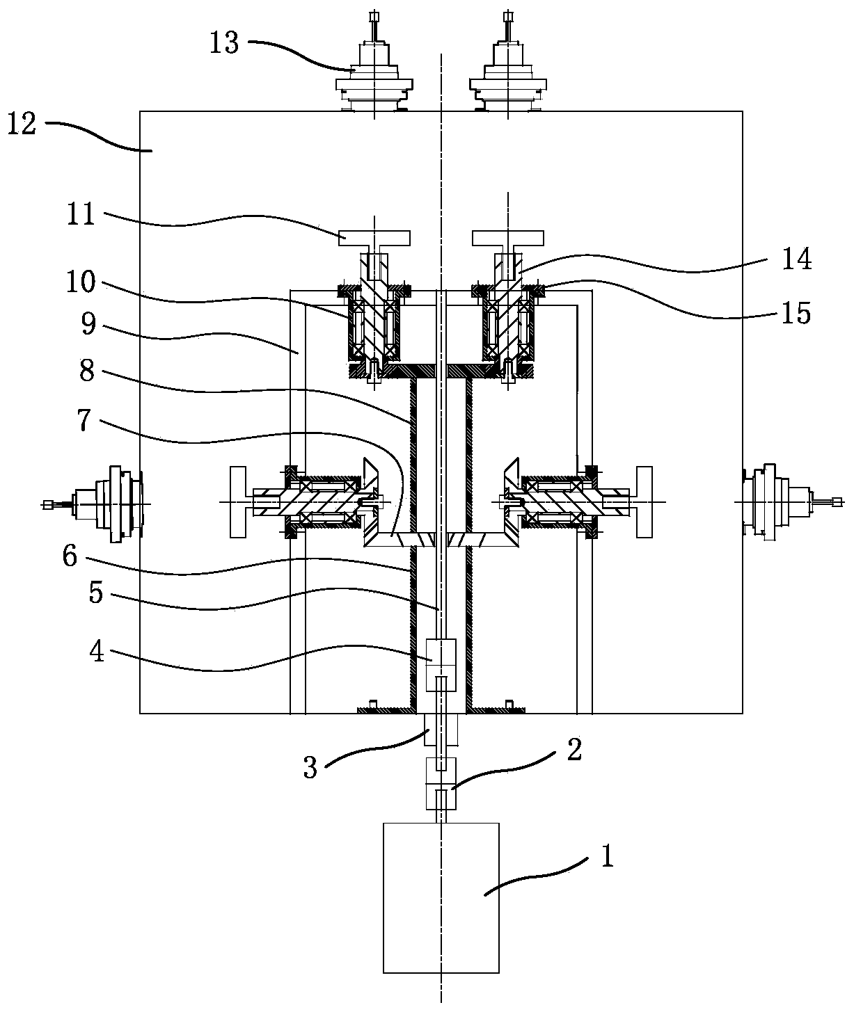
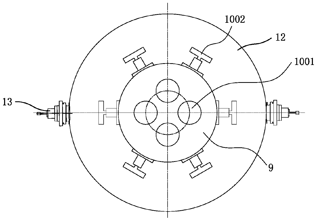
[0018] Now in conjunction with the accompanying drawings, the structure of the present invention will be further described. Such as Figure 1-Figure 5 As shown, the vacuum coating sample stage includes a power system, a planetary gear system, and a sample stage; the power system includes a power input shaft 5, a shaft coupling device, a dynamic sealing device 3, and a motor 1, and the shaft coupling device includes a second shaft coupling 4 and the first coupling 2, the power input shaft 5, and the main shaft of the motor are respectively connected to the central shaft of the dynamic sealing device through the first coupling and the second coupling, and the power input shaft and the main shaft of the motor are respectively connected through the coupling The device is connected with the central shaft of the dynamic sealing device to form the power system of the whole device. The dynamic sealing device and the motor are fixed on the outside of the vacuum chamber 12; the planetar...


PUM


Abstract

The invention relates to a vacuum coating sample stage, which is designed to ensure uniform coating of all sides of the same sample and uniform coating of samples in different positions of conventional like products. The vacuum coating sample stage is characterized in that a power system of the vacuum coating sample stage comprises a power input shaft, a coupling device, a dynamic sealing device and a motor, wherein the power input shaft and a main shaft of the motor are connected with a central shaft of the dynamic sealing device through the coupling device and fixed on the outer side of a vacuum cavity; a planet gear system comprises a sun gear component and a planet gear component, as well as a planet carrier; the planet gear component comprises a planet gear axle, a gland, a shaft guide sleeve, a bearing, a bearing retaining ring and a planet gear, as well as a gear limiting stop; the sun gear component is fixed on the inner side of the vacuum cavity; the shaft guide sleeve of theplanet gear component is fixed on the planet carrier through the gland; the planet gear of the planet gear component is meshed with a second sun gear of the sun gear component; the sample stage is fixed at the top end of the planet gear axle; and an arc source target material is arranged on the outer side of the vacuum cavity.

Description

technical field [0001] The invention relates to the technical field of vacuum coating in mechanical transmission engineering, in particular to a vacuum coating sample table. Background technique [0002] As an environment-friendly green surface protection technology, vacuum coating is more and more favored by enterprises. Compared with traditional electroplating, chemical plating and other technologies, the key advantage of vacuum coating lies in zero emission and zero pollution during the coating process, but the cost of coating equipment is high, low efficiency, poor uniformity, and it is difficult to achieve industrialization. Common coating samples are fixed on a stationary sample stage and deposited onto the sample surface by target sputtering. For multiple samples at different positions, it is difficult to ensure consistent sample film thickness, especially when depositing multilayer films on different targets. Sex is worse. In order to improve the uniformity, many m...

Claims


Application Information

Patent Timeline
Patent Type & Authority Patents(China)
IPC IPC(8): C23C14/32C23C14/50
CPCC23C14/325C23C14/505
Inventor 常秋香胡方勤赵浩杰
Owner 永州京辉科技有限公司
Why Eureka
Try Eureka