Hydraulic driving air compressor

A technology for driving air and compressors, used in machines/engines, liquid variable capacity machinery, mechanical equipment, etc., can solve the problems of difficult processing, increased piston movement resistance, high energy consumption, etc., to achieve no impact vibration, volume Compact, highly integrated effects

Active Publication Date: 2018-10-12
深圳市凯福机电设备有限公司
View PDF4 Cites 5 Cited by
  • Summary
  • Abstract
  • Description
  • Claims
  • Application Information

AI Technical Summary

Problems solved by technology

The use of springs increases the resistance when the piston moves, and the air is no longer compressed during the recovery process of the mover, so there is a defect of low system efficiency
There is also a screw air compressor, which is difficult to process and requires special lubricating oil for lubrication and sealing during

Method used


Image

  • Hydraulic driving air compressor

Examples


Embodiment Construction

[0012] The present invention will be further described in detail below in conjunction with the accompanying drawings and embodiments.

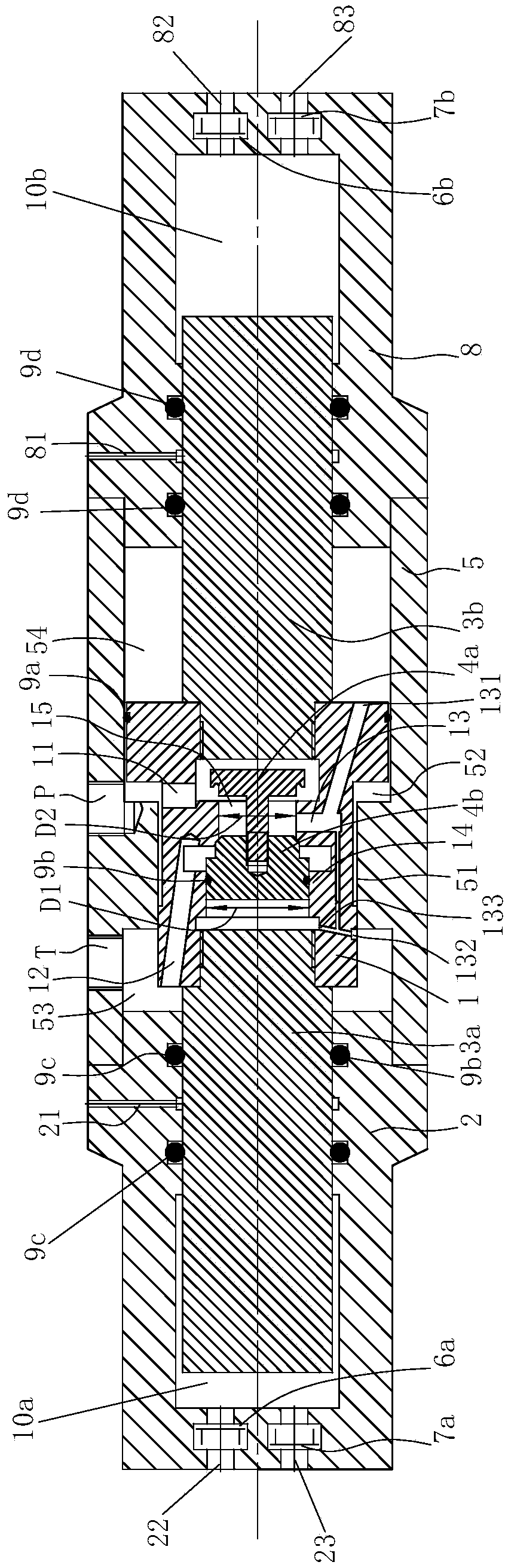
[0013] like figure 1 Shown is a preferred embodiment of the present invention.

[0014] A hydraulically driven air compressor comprising

[0015] A valve casing 5 with an axial hole, an oil inlet P and an oil return port T connected to the axial hole are opened on the side wall of the valve casing 5, and the middle part of the inner hole wall of the valve casing 2 has a first annular inner shoulder blade 51. The oil port P and the oil return port T are located on the left and right sides of the first annular inner shoulder blade 51;

[0016] The left cylinder body 2 with the left air chamber 10a and the right cylinder body 8 with the right air chamber 10b are respectively connected to the left and right ends of the axial channel of the valve casing 5, and the left cylinder body 2 is provided with a left air inlet 23 and a left air inlet. Ai...


PUM


Abstract

The invention relates to a hydraulic driving air compressor. The hydraulic driving air compressor is characterized by comprising a valve shell, a left cylinder body provided with a left air chamber, aright cylinder body provided with a right air chamber, a piston which is provided with an axial channel and in a T shape, a large valve core, a small valve core, a left plunger and a right plunger, wherein the diameter of the large valve core is greater than the diameter of a valve opening; and the left plunger is arranged in the left cylinder body and can slide left to right, the inner end of the left plunger is connected with the left end of the axial channel of the piston and can slide left to right along with the piston, and the inner end of the right plunger is connected with the right end of the axial channel of the piston and can slide left to right along with the piston. The air compressor has high integration degree and compact volume; and because the second outlet end of a firstthrough-flow hole communicates with an oil returning cavity and a left piston cavity, a certain distance is arranged from each of the left and right ends of the piston to the bottom surface of the corresponding cylinder body, and in this way, the fact that reversing of a liquid-controlled reversing valve assembly can be completed before the piston collides with two end covers is ensured, therefore, non-impact vibration and less noise are achieved.

Description

technical field [0001] The invention belongs to an air compressor, in particular to a hydraulically driven air compressor. Background technique [0002] The air compressor is a reciprocating compressor, which has various structural forms, one of which is to use an ordinary rotating motor to compress the gas by driving the piston to reciprocate in the cylinder through the crank-link mechanism. When the piston performs a compression stroke, the suction valve is closed and the exhaust valve is opened. When the piston is in the suction stroke, the exhaust valve is closed and the suction valve is opened. The working compression ratio of this kind of compressor is small, the stroke of its reciprocating motion is relatively short, the vibration and noise are large during operation, and it is easy to wear, and the structure is complicated from rotary motion to linear motion, the efficiency is low, and there is noise when the mechanical transmission mechanism is working. big. The ...

Claims


Application Information

Patent Timeline
IPC IPC(8): F04B35/02F04B31/00F04B49/00F04B39/00F04B39/10
CPCF04B31/00F04B35/00F04B39/0005F04B39/10F04B49/002
Inventor 邵玉刚
Owner 深圳市凯福机电设备有限公司
Why Eureka
Try Eureka