Spraying and microwave sintering-forming method for superfine particle carrier liquid

A microwave sintering, ultra-fine particle technology, applied in the direction of additive processing, etc., can solve the problems of poor precision of formed parts and secondary processing, and achieve the effect of strong consistency, uniformity, and easy realization.

Inactive Publication Date: 2018-10-16
沈阳精合数控科技开发有限公司
View PDF9 Cites 2 Cited by
  • Summary
  • Abstract
  • Description
  • Claims
  • Application Information

AI Technical Summary

Problems solved by technology

The metal 3D printing rapid prototyping technology mentioned above also has disadvantages such a

Method used


Image

  • Spraying and microwave sintering-forming method for superfine particle carrier liquid
  • Spraying and microwave sintering-forming method for superfine particle carrier liquid

Examples


Embodiment 1

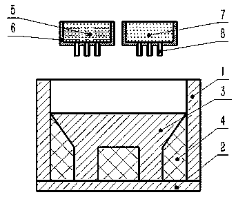
[0046] Prepared by the preparation method described in this example figure 1 The shown parts specifically include the following steps:

[0047] S1. Establish the solid 3D model of the part to be printed and the 3D model of the process support structure through 3D software;

[0048] S2. Use slicing software to slice the 3D model, set the manufacturing parameters, and compile the process control program;

[0049] S3. Mix the metal powder TC4 with an average particle size of 0.01 mm and the dispersant polyethylene glycol 400 (PEG 400) in a ratio of 80:20 to form a metal spray liquid, which is placed in a metal spray tank; the average particle size is The 0.01mm support material polyphenylene sulfide (PPS) is placed in the support spray tank;

[0050] S4. According to the set process control program: the injection power is 200 w, the injection speed is 3.5 m / s, and the thickness of the slice layer is 0.01 mm. The metal injection liquid and the support material are injected layer...

Embodiment 2

[0055] As another embodiment of the above example, the following preparation method is used in this example to prepare figure 1 The shown parts specifically include the following steps:

[0056] S1. Establish the solid 3D model of the part to be printed and the 3D model of the process support structure through 3D software;

[0057] S2. Use slicing software to slice the 3D model, set the manufacturing parameters, and compile the process control program;

[0058] S3. Mix the metal powder TA15 with an average particle size of 0.007 mm and the dispersant polyethylene glycol 400 (PEG 400) in a ratio of 75:25 to form a metal spray liquid, which is placed in a metal spray tank; the average particle size is The 0.007mm support material polyphenylene sulfide (PPS) is placed in the support spray tank;

[0059] S4. According to the set process control program: the injection power is 175 w, the injection speed is 3.0 m / s, and the thickness of the slice layer is 0.01 mm. The metal inject...

Embodiment 3

[0064] As another embodiment of the above example, the following preparation method is used in this example to prepare figure 1 The shown parts specifically include the following steps:

[0065] S1. Establish the solid 3D model of the part to be printed and the 3D model of the process support structure through 3D software;

[0066] S2. Use slicing software to slice the 3D model, set the manufacturing parameters, and compile the process control program;

[0067] S3. Mix the metal powder GH3625 with an average particle size of 0.015 mm and the dispersant polyethylene glycol 400 (PEG 400) in a ratio of 90:10 to form a metal spray liquid, which is placed in a metal spray tank; the average particle size is The 0.014mm support material polyphenylene sulfide (PPS) is placed in the support spray tank;

[0068] S4. According to the set process control program: the injection power is 400 w, the injection speed is 6 m / s, and the thickness of the slice layer is 0.02 mm. The metal inject...


PUM

PropertyMeasurementUnit
The average particle sizeaaaaaaaaaa

Abstract

The invention relates to a spraying and microwave sintering-forming method for superfine particle carrier liquid. The spraying and microwave sintering-forming method comprises the following steps of:establishing a solid three-dimensional model of a to-be-printed part and a three-dimensional model of a process supporting structure through three-dimensional software; slicing the three-dimensional model by slicing software, setting manufacturing parameters, and compiling process control program; uniformly mixing metal powder with a dispersing agent in proportion to form metal spraying fluid, andputting the metal spraying fluid into a metal spraying tank; putting a supporting material into a supporting and spraying tank; enabling a plurality of spraying heads to separately spray the metal spraying fluid and the supporting material to a base plate of a forming region layer by layer according to set process control program, thereby manufacturing a formed part; putting the formed part at atemperature higher than a melting point of the supporting material, and melting to remove support; heating the part to a temperature being 900-1300 DEG C through microwaves, and sintering-forming theprocessed printed part; and performing post-treatment on the sintered and formed part to obtain a final finished product part. The spraying and microwave shielding and forming method is safe in cleaning, and can guarantee uniformity of the part.

Description

technical field [0001] The invention relates to a microwave sintering forming method of ultrafine particle carrier liquid injection, which belongs to the technical field of 3D printing. Background technique [0002] At present, metal 3D printing rapid prototyping technologies mainly include selective laser melting (SLM), selective laser sintering (SLS), laser cladding (LCF) and laser deposition modeling (LDM) technologies, etc. The characteristics of forming have been widely used in aerospace, military, medical, industrial modeling, machinery manufacturing, construction, film and television, home appliances, light industry, archaeology, culture and art, sculpture, jewelry and other fields. [0003] However, the above-mentioned 3D printing laser forming technologies all need to use laser as the energy source for metal melting or sintering. The forming method is layer-by-layer sintering, and the longitudinal and transverse properties of the formed parts are quite different. I...

Claims


Application Information

Patent Timeline
IPC IPC(8): B22F3/22B22F3/105B33Y10/00
Inventor 郭明海李广生李澄葛青龚天才孙升斌李波李怡超闫琦李欣红
Owner 沈阳精合数控科技开发有限公司
Why Eureka
Try Eureka