Numerical control laser engraving machine, control system, control method and computer

A technology of numerical control laser and control method, applied in laser welding equipment, manufacturing tools, welding equipment and other directions, can solve the problems of small calculation amount, inability to effectively improve production efficiency, poor accuracy of 3D-based CAD drawing data, etc.

Inactive Publication Date: 2018-10-16
GUANGDONG TECHN COLLEGE OF WATER RESOURCES & ELECTRIC ENG
View PDF5 Cites 5 Cited by
  • Summary
  • Abstract
  • Description
  • Claims
  • Application Information

AI Technical Summary

Problems solved by technology

[0007] When engraving objects, traditional engraving uses EDM, corrosion, mechanical engraving and printing and other processing methods. Traditional processing methods have many disadvantages. Harmful gases will be generated during the production process, causing damage to the environment;
[0008] Moreover, traditional processing methods cannot be mass-produced, require a large amount of manpower, spend a lot of time and financial resources, cannot effectively improve production efficiency, and are not conducive to the development of enterprises
[0009] In the prior art, the stereo vision method requires less calculation, but there are blank areas in the disparity map obtained in the flat area of ​​the image texture, so the calculated point cloud density is very low; the motion structure method has high universality , which includes the derivation process from sparse point cloud to dense point cloud, but the density of the obtained dense point cloud still depends on the texture complexity of the image. For images with flat texture, the obtained point cloud density is relatively low; based on depth The image reconstruction method has high precision and does not require the complexity of the image texture. However, this method is highly sensitive to the accuracy of the depth camera and is currently not suitable for 3D reconstruction of finely carved objects.
The accuracy of the 3D base CAD data obtained by the existing technology is poor

Method used


Image

  • Numerical control laser engraving machine, control system, control method and computer
  • Numerical control laser engraving machine, control system, control method and computer
  • Numerical control laser engraving machine, control system, control method and computer

Examples


Embodiment Construction

[0079] In order to further understand the content, features and effects of the present invention, the following examples are given, and detailed descriptions are given below with reference to the accompanying drawings.

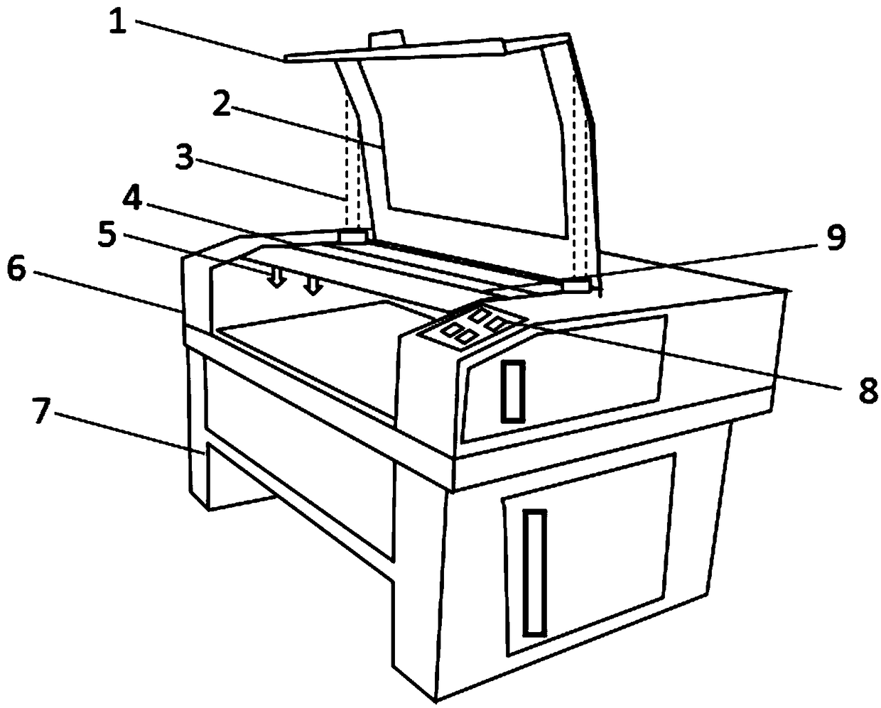
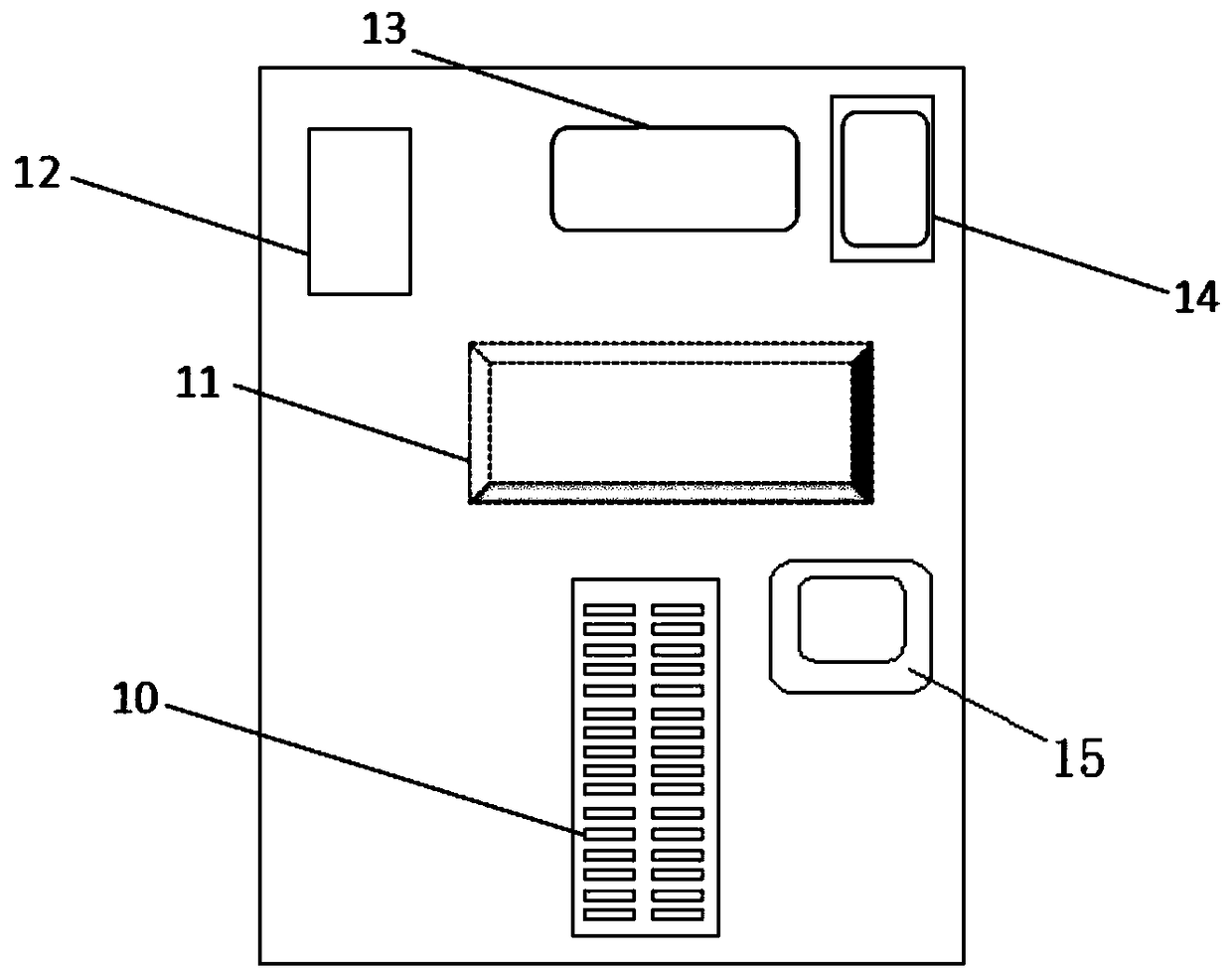
[0080] Such as figure 1 and figure 2 As shown, the CNC laser engraving machine provided by the embodiment of the present invention includes: a cover plate 1; a transparent baffle plate 2, a support rod 3, a guide rail 4, a laser device 5, a casing 6, a base 7, a control panel 8, and a horizontal bar 9 core board modules 10 (Arduino Uno R3 core board), signal processor 11, motor 12, graphics processing module 13, single-chip microcomputer 14.

[0081] The cover plate 1 is welded on the top of the shell 6 through the rotating shaft, the transparent baffle 2 is keyed in the middle of the cover plate 1, the head of the support rod 3 is welded on the cover plate 1, and the tail is welded on the top of the shell 6. In the recess, the two ends of the guide rail 4...


PUM


Abstract

The invention belongs to the technical field of numerical control engraving, and discloses a numerical control laser engraving machine, a control system, a control method and a computer. The control method comprises the steps that a set of circularly photographing graph sequences are obtained through a camera through a CAD graphic module, so that CAD engraving graphic data of a to-be- engraved product is obtained; moreover, the data are preprocessed through a signal processor and then are sent to a graphic processing module for analysis of the CAD engraving graphic data of the to-be-engraved product; the analyzed data is input into a single-chip microcomputer to be compiled by an engraving program; and an instruction of the compiled program is sent to a core board module, an instruction motor drives a laser to slide back and forth in a guide rail, and engraving of the whole graph is completed. According to the numerical control laser engraving machine, the control system, the control method and the computer, fine engraving can be carried out by utilizing laser, a computer numerical control technology is used and can be well combined with a laser processing system so that requirements for industrial mass production can be met, the production efficiency can be effectively improved, moreover, by using laser processing, the environment can be prevented from being polluted, and thepracticability and the generalization performance are good.

Description

technical field [0001] The invention belongs to the technical field of numerical control engraving, and in particular relates to a numerical control laser engraving machine, a control system and a control method, and a computer. Background technique [0002] At present, the existing technologies commonly used in the industry are as follows: [0003] At present, when engraving objects, the traditional engraving uses EDM, corrosion, mechanical scribing, printing and other processing methods. The traditional processing methods have many disadvantages. Harmful gases will be generated during the production process, which will cause environmental damage. Destruction, and traditional processing methods cannot be mass-produced, require a large amount of manpower, spend a lot of time and financial resources, cannot effectively improve production efficiency, and are not conducive to the development of enterprises. [0004] Computer vision involves many disciplines and is the inverse...

Claims


Application Information

Patent Timeline
Patent Type & Authority Applications(China)
IPC IPC(8): B23K26/362B23K26/70
CPCB23K26/361B23K26/702
Inventor 李殊骁邵忠良黄诚刘江帆邓桂芳
Owner GUANGDONG TECHN COLLEGE OF WATER RESOURCES & ELECTRIC ENG
Why Eureka
Try Eureka