A single crystal silicon rod cutting machine

A single crystal silicon rod and cutting machine technology, which is applied in the direction of manufacturing tools, stone processing equipment, fine working devices, etc., can solve the problems of reduced work efficiency, large errors, single crystal silicon rod defects, etc., to achieve automatic operation, Adjust the effect of improving efficiency and improving cutting quality

Active Publication Date: 2020-03-27
SHANDONG DAHAI NEW ENERGY DEV
View PDF9 Cites 0 Cited by
  • Summary
  • Abstract
  • Description
  • Claims
  • Application Information

AI Technical Summary

Problems solved by technology

The disadvantages of this adjustment method are: the adjustment method is manual adjustment, which is not only time-consuming and laborious, but also depends entirely on human eyes to judge whether the adjustment is in place, and the error is large
[0004] In addition, during the cutting process of single crystal silicon rods in the prior art, the silicon rods are usually placed directly in the V-shaped grooves used to hold the single crystal silicon rods, or fixed by the operator manually pulling the jig. The method makes the monocrystalline silicon rods it cuts have defects
Due to the limited manpower, the silicon rod cannot be completely fixed firmly, resulting in the problem of "wavy surface and uneven surface" on the truncated surface of the silicon rod when the diamond saw blade cuts the crystal rod, which affects the product quality and reduces the work efficiency

Method used


Image

  • A single crystal silicon rod cutting machine
  • A single crystal silicon rod cutting machine
  • A single crystal silicon rod cutting machine

Examples


Embodiment 1

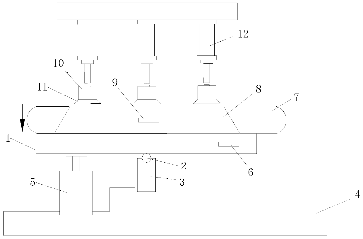
[0035] Such as Figure 1 to Figure 3 As shown, a single crystal silicon rod cutting machine includes a workbench 1 for supporting the single crystal silicon rod 7 . The cutter also includes a control unit.

[0036] The cutting machine also includes a position detection unit for detecting the inclination between the axial direction of the single crystal silicon rod 7 and the cutting direction of the saw blade of the cutting machine, wherein figure 1 The direction of the arrow in shows the cutting direction of the saw blade of the cutter. Preferably, the position detection unit is a biaxial inclination sensor, and the biaxial inclination sensor is arranged on the workbench 1 at a position capable of contacting the single crystal silicon rod 7 . The two-axis inclination sensor is connected in communication with the control unit.

[0037] The cutting machine also includes an adjustment unit, which is used to adjust the horizontal position and the height position of the workbenc...

Embodiment 2

[0053] The structure and principle of this embodiment and embodiment 1 are basically the same, the difference is:

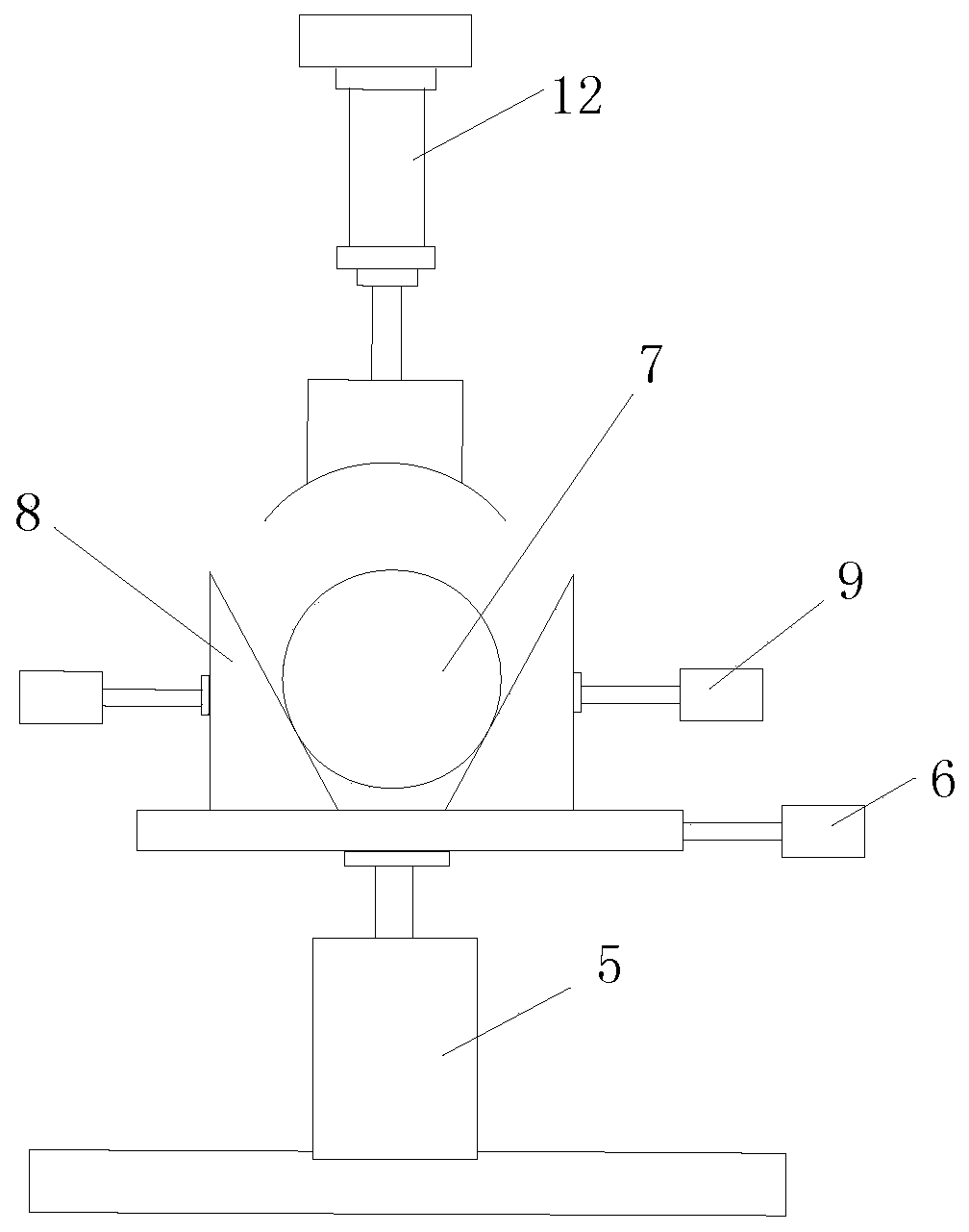
[0054] Such as Figure 4 with Figure 5 As shown, in this embodiment, there are two workbench lifting adjustment mechanisms 5, which are respectively arranged under the front and rear of the workbench 1, and the workbench horizontal displacement adjustment mechanism 6 has two Two, which are respectively arranged on one side of the front and rear of the workbench 1 (the "side" refers to the left or right side of the workbench), so as to achieve faster adjustment.

[0055] Parts not mentioned in this application can be realized by adopting or referring to existing technologies.


PUM


Abstract

This invention discloses a monocrystalline silicon rod guillotine, and belongs to the technical field of monocrystalline silicon rod processing. The monocrystalline silicon rod guillotine includes a worktable, a clamping unit, an adjusting unit and a controlling unit, wherein the worktable is used for supporting monocrystalline silicon rods; the clamping unit is used for clamping and positioning the monocrystalline silicon rods; the adjusting unit is used for adjusing the horizontal position and the height position of the worktable to allow the axial direction of the monocrystalline silicon rods located on the worktable to be perpendicular to the cutting direction of the saw blade of the guillotine; and the controlling unit is used for controlling the clamping unit and the adjusting unit.The monocrystalline silicon rod guillotine is particularly suitable for cutting and processing of the monocrystalline silicon rods with different size and front-and-back inconsistent thickness.

Description

technical field [0001] The application belongs to the technical field of single crystal silicon rod processing, and in particular relates to a single crystal silicon rod cutting machine. Background technique [0002] The method of producing monocrystalline silicon is usually to grow rod-shaped monocrystalline silicon from the melt by Czochralski method or suspension zone melting method, and the cross section of monocrystalline silicon is circular. In order to conveniently meet the shape and size of silicon wafers in the production process, it is necessary to cut off monocrystalline silicon rods. Cutting off single crystal silicon rods is an indispensable step in the early stage of the production of semiconductor devices. At present, cutting single crystal silicon is to cut single crystal silicon Rod special equipment - single crystal cutting machine. [0003] Existing single crystal cutting machines generally include a base, transmission shaft parts, cutters and monocrystal...

Claims


Application Information

Patent Timeline
Patent Type & Authority Patents(China)
IPC IPC(8): B28D5/00B28D5/02
CPCB28D5/0058B28D5/0082B28D5/022
Inventor 贾哲古海军
Owner SHANDONG DAHAI NEW ENERGY DEV
Why Eureka
Try Eureka