Boiler flue gas energy-saving white plume elimination device

A boiler flue gas and whitening technology, applied in the field of energy conservation and environmental protection, can solve the problems of white smoke from chimneys, water loss to the environment, energy loss, etc., and achieve the effects of reducing water consumption, improving dust removal efficiency, and fully recycling

Pending Publication Date: 2018-10-19
北京兴晟科技有限公司
View PDF5 Cites 3 Cited by
  • Summary
  • Abstract
  • Description
  • Claims
  • Application Information

AI Technical Summary

Problems solved by technology

[0002] In the existing boiler flue gas treatment system, the flue gas generated by the boiler usually passes through the air preheater, dust collector, induced draft fan, and desulfurization absorption tower in sequence, and then is discharged into the chimney and enters the atmosphere; Part of the waste heat of the flue gas will be recovered in the desulfurization tower, but due to the low-temperature corrosion of the air preheater, the temperature of the flue gas discharged from the outlet of the air preheater is still high, so the temperature of the flue gas entering the desulfurization tower is still high, absorbing The desulfurization slurry in the tower will absorb a large amount of latent heat of vaporization, and part of the water will be evaporated and discharged into the atmosphere along with the flue gas. In addition, due to the high temperature of the flue gas discharged into the atmosphere, a large amount of latent heat of vaporization carried by water vapor and Sensible heat is discharged into the atmosphere, causing energy loss, and carrying a large amount of water, causing water loss and environmental pollution, resulting in serious white smoke from the chimney

Method used


Image

  • Boiler flue gas energy-saving white plume elimination device
  • Boiler flue gas energy-saving white plume elimination device
  • Boiler flue gas energy-saving white plume elimination device

Examples


Embodiment Construction

[0025] In order to have a clearer understanding of the technical features, purposes and effects of the present invention, the specific implementation manners of the present invention will now be described with reference to the accompanying drawings. Wherein, the same parts adopt the same reference numerals.

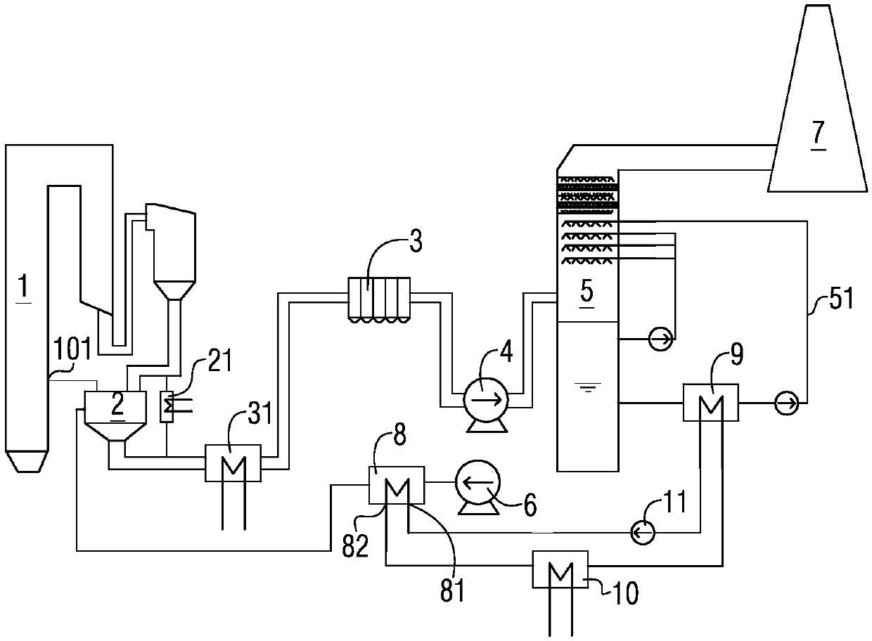
[0026] figure 1 It is a schematic structural principle diagram of a boiler flue gas energy saving and whitening device according to a specific embodiment of the present invention. see figure 1 As shown, the present invention provides a boiler flue gas energy-saving and whitening device, which includes a boiler 1 and an air preheater 2 sequentially connected to the boiler 1 through a flue, a dust collector 3, an induced draft fan 4, and a desulfurization absorption tower 5. Chimney 7, the air preheater 2 is connected with the air inlet 101 of the boiler 1 and the blower 6 respectively through the air supply pipe, the inlet or outlet of the blower 6 is provided with a blo...


PUM


Abstract

The invention provides a boiler flue gas energy-saving white plume elimination device. The device comprises a boiler, and an air preheater, a dust collector, an induced draft fan, a desulfurization absorber tower and a chimney sequentially connected to the boiler through a flue. An air inlet and a blower of the boiler is connected to the air preheater through a air blow duct, a blower heater is provided at an inlet or an outlet of the blower, a heat medium water inlet and a heat medium water outlet is provided at the blower heater, the heat medium water inlet and the heat medium water outlet are sequentially connected to the flue gas residual heat exchanger and the heat medium water cooling device through a heat medium water pipe, and a heat medium water power driving device is provided atthe heat medium water pipe. The boiler flue gas energy-saving white plume elimination device provided by the the invention can not only fully recover the waste heat of the flue gas, but also has theobvious heat pump function, and can improve the grade and utilization efficiency of the recovered heat energy.

Description

technical field [0001] The invention relates to the field of energy saving and environmental protection, in particular to an energy saving and whitening device for boiler flue gas. Background technique [0002] In the existing boiler flue gas treatment system, the flue gas produced by the boiler usually passes through the air preheater, dust collector, induced draft fan, and desulfurization absorption tower in sequence, and then is discharged into the chimney and enters the atmosphere; Part of the waste heat of the flue gas will be recovered in the desulfurization tower, but due to the low-temperature corrosion of the air preheater, the temperature of the flue gas discharged from the outlet of the air preheater is still high, so the temperature of the flue gas entering the desulfurization tower is still high, absorbing The desulfurization slurry in the tower will absorb a large amount of latent heat of vaporization, and part of the water will be evaporated and discharged int...

Claims


Application Information

Patent Timeline
Patent Type & Authority Applications(China)
IPC IPC(8): F23J15/02F23J15/06
CPCF23J15/02F23J15/06Y02E20/30
Inventor 郭启刚李爱云郭泰
Owner 北京兴晟科技有限公司
Why Eureka
Try Eureka