
Light irradiation apparatus

A technology of light irradiation device and object to be treated, applied in the direction of cleaning flexible articles, electrical components, semiconductor/solid-state device manufacturing, etc. The effect of cleaning, improving airtightness, and suppressing the attenuation of ultraviolet rays

Active Publication Date: 2018-10-23
USHIO DENKI KK
View PDF6 Cites 0 Cited by
  • Summary
  • Abstract
  • Description
  • Claims
  • Application Information

AI Technical Summary

Problems solved by technology

[0013] And, the amount of air introduced into the periphery of the processing area (ultraviolet radiation space) along with the object to be processed depends on the conveying speed of the object to be processed, so the oxygen concentration in the ultraviolet radiation space varies for each object to be processed. As a result, there is a problem that the desired light cleaning effect cannot be stably obtained

Method used


Image

  • Light irradiation apparatus
  • Light irradiation apparatus
  • Light irradiation apparatus

Examples


Embodiment 1

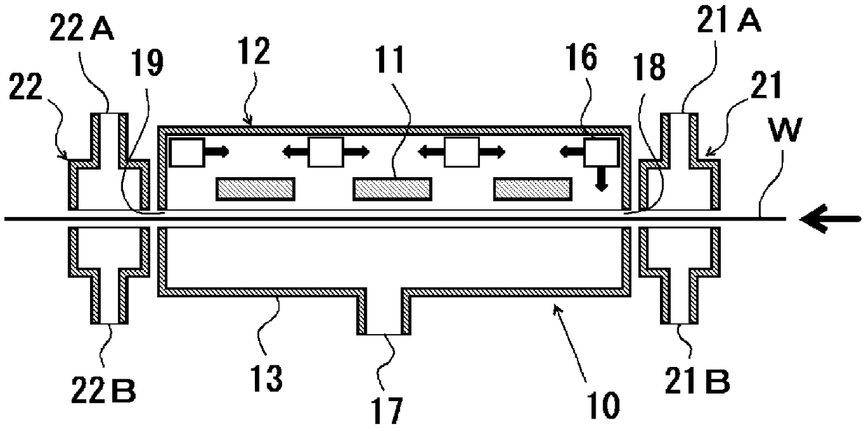
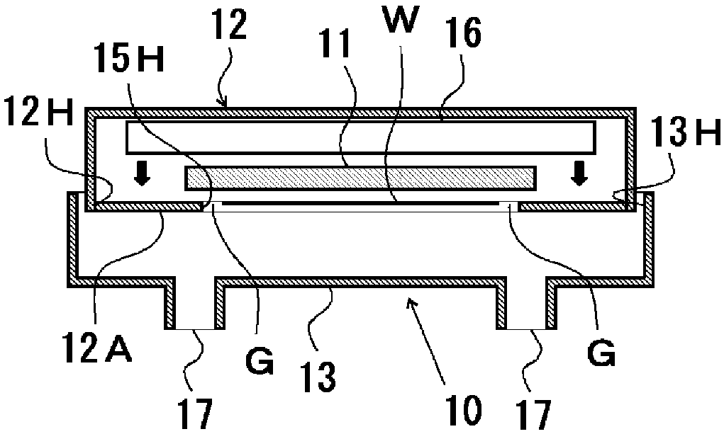
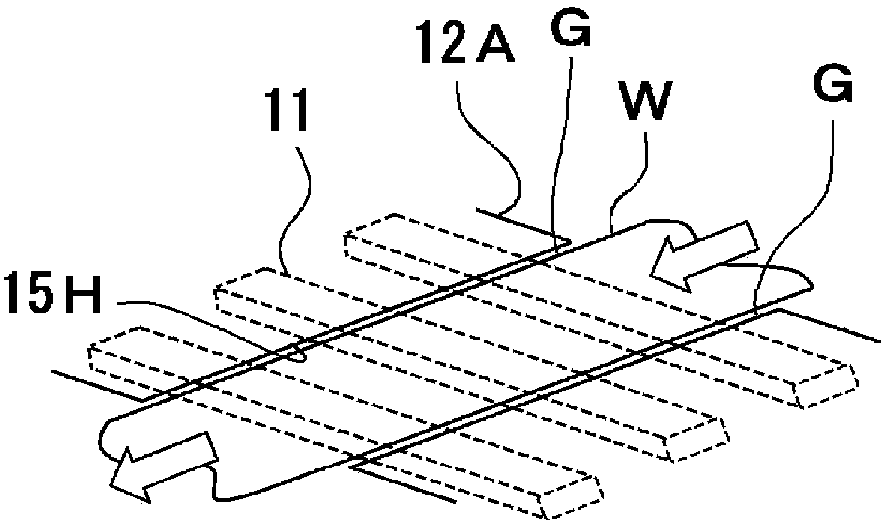
[0125] Made with Figure 1 ~ Figure 3 The structure of the light irradiation device [1]. Specifically, it is as follows.

[0126] Processing chamber; length of the object to be processed in the conveying direction: 445 mm, length of the object to be processed in the width direction: 1090 mm, distance between the processing area and the top surface of the lampshade: 72 mm, distance between the processing area and the exhaust space forming member The distance between the bases: 150mm, the distance (interval) of the narrow passage for gas flow resistance: 10mm

[0127] Ultraviolet lamp; type: xenon excimer lamp, center wavelength: 172nm, length: 640mm, effective irradiation width: 510mm, distance from the treatment area: 4mm

[0128] ・Pressure inside the lampshade: Positive pressure 2 Pa higher than the external atmosphere (atmospheric pressure)

[0129] ・Pressure inside the exhaust space forming member: Negative pressure 2 Pa lower than the external atmosphere (atmospheric pr...


PUM


Abstract

Provided is a light irradiation apparatus capable of performing light cleaning with high stability irrespective of the transport speed of an object to be processed. The light irradiation apparatus irradiates one surface of a band-like object to be processed which is transported along a transportation path with ultraviolet rays, and is characterized by comprising a lampshade having an opening alonga passing plane of one surface side of the object to be processed in the transport path; an ultraviolet lamp being provided in the lampshade and extending in a width direction of the object to be processed; a gas supply unit for supplying an inert gas into the lampshade; and an exhaust space forming member having an opening along a passing plane of the other surface side of the object to be processed in the transport path, wherein, a shielding body is provided at the opening of the lampshade and forms a gas flow resistance bottleneck between the shielding body and both side edge portions of the object to be processed.

Description

technical field [0001] The present invention relates to a light irradiation device for performing optical cleaning by irradiating ultraviolet rays to one surface of a belt-shaped object to be processed conveyed along a conveyance path. Background technique [0002] Photoashing of resists in the manufacturing process of semiconductors or liquid crystals, removal of resists adhering to the pattern surface of templates in nanoimprinting devices, glass substrates for liquid crystals, silicon wafers, etc. As for the dry cleaning treatment and the cleaning treatment of the bonded surface of the sheet-shaped film wound around the roll, a photocleaning (dry cleaning) method of irradiating ultraviolet rays is known. [0003] As a light irradiation device for performing such optical cleaning, for example, Patent Document 1 discloses a technique of irradiating vacuum ultraviolet rays to a glass substrate, and removing the glass substrate by the cleaning action of the vacuum ultraviolet...

Claims


Application Information

Patent Timeline
IPC IPC(8): B08B7/00B08B11/04
CPCB08B7/0057B08B11/04H01L21/67028H01L21/67213
Inventor 山森贤治吉原启太
Owner USHIO DENKI KK
Learn More