
A bioelectrochemical h 2 o 2 Sensors and their use to detect h 2 o 2 Methods

A bioelectrochemical and H2O2 technology, applied in the field of pollution detection, can solve problems such as difficult to use, increase the cost of sensor construction and use, and difficulties in practical application, and achieve the effects of wide detection range, low construction and use costs, and low cost

Active Publication Date: 2020-06-16
DALIAN MARITIME UNIVERSITY
View PDF6 Cites 0 Cited by
  • Summary
  • Abstract
  • Description
  • Claims
  • Application Information

AI Technical Summary

Problems solved by technology

Expensive equipment increases the cost of sensor construction and use, making it difficult for practical applications; it is even more difficult to use in remote areas or where sensor installation space is limited

Method used


Image

  • A bioelectrochemical h  <sub>2</sub> o  <sub>2</sub> Sensors and their use to detect h  <sub>2</sub> o  <sub>2</sub> Methods

Examples


Embodiment 1

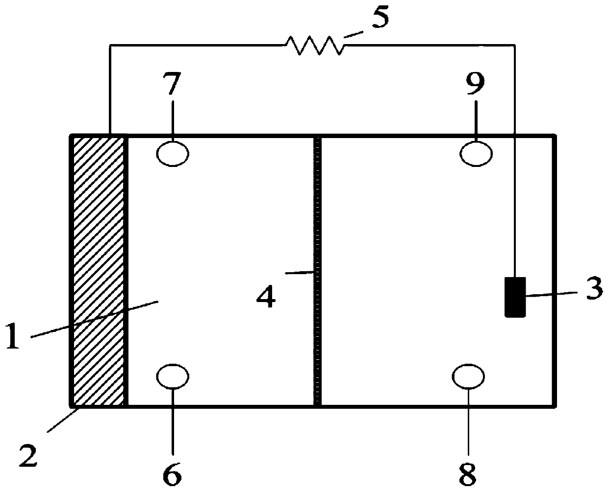
[0033] A bioelectrochemical H 2 o 2 sensors such as figure 1 As shown, the bioelectrochemical H 2 o 2 The sensor includes a sensor housing 1, a biological anode 2, an electrochemical cathode 3, a cation exchange membrane 4, and an external load 5;

[0034] The cation exchange membrane 4 is arranged in the sensor housing 1, and the sensor housing 1 is divided into an anode chamber and a cathode chamber;

[0035] The bioanode 2 is a carbon fiber brush, and the pretreatment method of the bioanode 2 is: firstly, it is cleaned with isopropanol, then heat-treated at 450°C for 60 minutes, and then operated in a microbial fuel cell for 3 months to fully enrich and generate electricity Microorganisms form an electrochemically active biofilm to obtain stable anode electricity generation performance, and the electrons generated by the anode are transferred to the surface of the cathode through an external circuit to participate in the H 2 o 2 Catalytic reduction reaction to form an...

Embodiment 2

[0039] A kind of utilizing the sensor described in embodiment 1 to detect H 2 o 2 The method, described method comprises the steps:

[0040] H was injected into the cathode chamber and the anode chamber with known different concentrations at the same flow rate through a peristaltic pump. 2 o 2 Solution and anolyte, wherein, the flow rate is 5mL / min, and the anolyte is a solution containing sodium acetate and glucose;

[0041] Connect the circuit, use the data acquisition instrument to record the sensor current response output value, and obtain the current response and H 2 o 2Concentration-related standard curve, the linear response fitting equation is: I (mA) = 1.0952 + 0.1984lnC (mmol L -1 ), correlation coefficient (R 2 ) is 0.9969, and the detection sensitivity is 198.4μAmM -1 ;

[0042] According to containing H 2 o 2 The response current value measured by the sample to be tested is compared with the standard curve to obtain H 2 o 2 concentration.


PUM

PropertyMeasurementUnit
electrical resistanceaaaaaaaaaa

Abstract

The invention relates to a bioelectrochemical H2O2 sensor and a method using the bioelectrochemical H2O2 sensor for detecting H2O2, and belongs to the field of pollution detection. The bioelectrochemical H2O2 sensor comprises a sensor housing, a bioanode, an electrochemical cathode, an ion exchange membrane, and an external load; and the ion exchange membrane is disposed in the sensor housing to divide the sensor housing into an anode chamber and a cathode chamber. The bioanode is disposed in the anode chamber, the lower portion of the anode chamber is provided with an anolyte inlet, the upperportion of the anode chamber is provided with an anolyte outlet; the electrochemical cathode is disposed in the cathode chamber, and the lower portion of the cathode chamber is provided with an inletfor a cathode to-be-detected H2O2 solution, the upper portion of the cathode chamber is provided with a cathode liquid outlet; one end of the external load is connected to the bioanode, and the otherend of the external load is connected to the electrochemical cathode. The bioelectrochemical H2O2 sensor has rapid response, high sensitivity and wide detection range of H2O2 concentration.

Description

technical field [0001] The invention relates to a bioelectrochemical H 2 o 2 Sensor and its use to detect H 2 o 2 The method belongs to the field of pollution detection. Background technique [0002] In recent years, hydrogen peroxide (H 2 o 2 ) testing requirements continue to increase. h 2 o 2 In the detection method, H 2 o 2 Sensors are used in numerous studies due to their high efficiency, high selectivity, and high sensitivity. [0003] h 2 o 2 Sensors can be divided into two broad categories: enzymatic sensors and non-enzymatic sensors. Enzymatic sensors use immobilized enzymes (such as: horseradish peroxidase, hemoglobin, catalase) to modify electrodes to construct H 2 o 2 sensor. Although the enzymatic sensor has high sensitivity, the immobilization process of the enzyme is complicated, and the requirements for the immobilized modified carrier electrode material are strict. During the modification and use, the enzyme easily loses its catalytic activit...

Claims


Application Information

Patent Timeline
Patent Type & Authority Patents(China)
IPC IPC(8): G01N27/416
CPCG01N27/4166
Inventor 刘伟凤朱益民尹琳周子皓郑立彪金琪
Owner DALIAN MARITIME UNIVERSITY
Learn More