Beamsplitter for achieving grazing incidence of light

A technology of beam splitter and light incidence, which is applied in the field of optical systems, can solve the problems of increasing absorption loss, avoid layer degradation, reduce manufacturing effort and cost, and reduce the total number of effects

Pending Publication Date: 2018-10-23
CARL ZEISS SMT GMBH
View PDF24 Cites 0 Cited by
  • Summary
  • Abstract
  • Description
  • Claims
  • Application Information

AI Technical Summary

Problems solved by technology

[0008] In practice, however, the problem frequently arises that, in order to cover a larger wavelength range, in principle a very large number of different dielectric layers is necessary, which in turn involves an accompanying increase in the proportion of stray light due to the large number of interfaces and in particular in e.g. Increased absorption loss at low wavelengths less than 150nm

Method used


Image

  • Beamsplitter for achieving grazing incidence of light
  • Beamsplitter for achieving grazing incidence of light
  • Beamsplitter for achieving grazing incidence of light

Examples


Embodiment Construction

[0035] Figure 12 Only a schematic illustrating the design of a conventional bright-field reflected light microscope is shown.

[0036] exist Figure 12 In the design of the bright-field reflected light microscope schematically shown in , the illumination light is incident on the beam splitter 10, is reflected in a proportion at its first interface 10a and is transmitted in a proportion. The reflected scale passes through the microscope objective 15 to the object plane OP, is reflected at the sample to be investigated located in the object plane OP, is again scaled and then transmitted through the beam splitter 10, via its second interface 10b to the detector 20.

[0037] The invention is not limited to implementation in such microscopes. For example, the invention or a beam splitter with a design according to the invention can also be implemented in other applications, for example for inspecting reticles or Mask inspection system for masks.

[0038] The following will ref...


PUM

PropertyMeasurementUnit
thicknessaaaaaaaaaa
angle of incidenceaaaaaaaaaa

Abstract

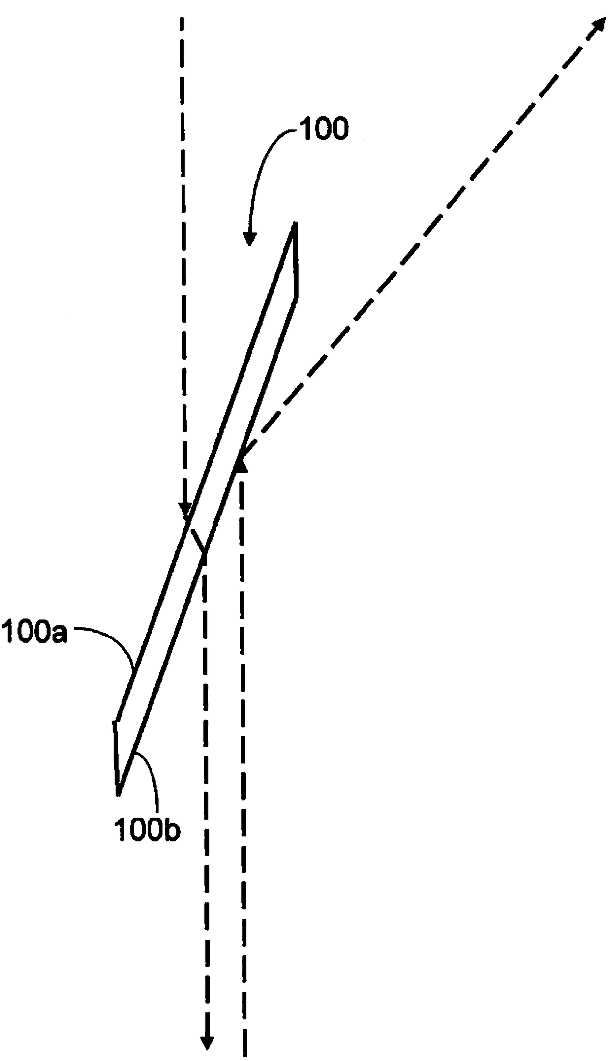
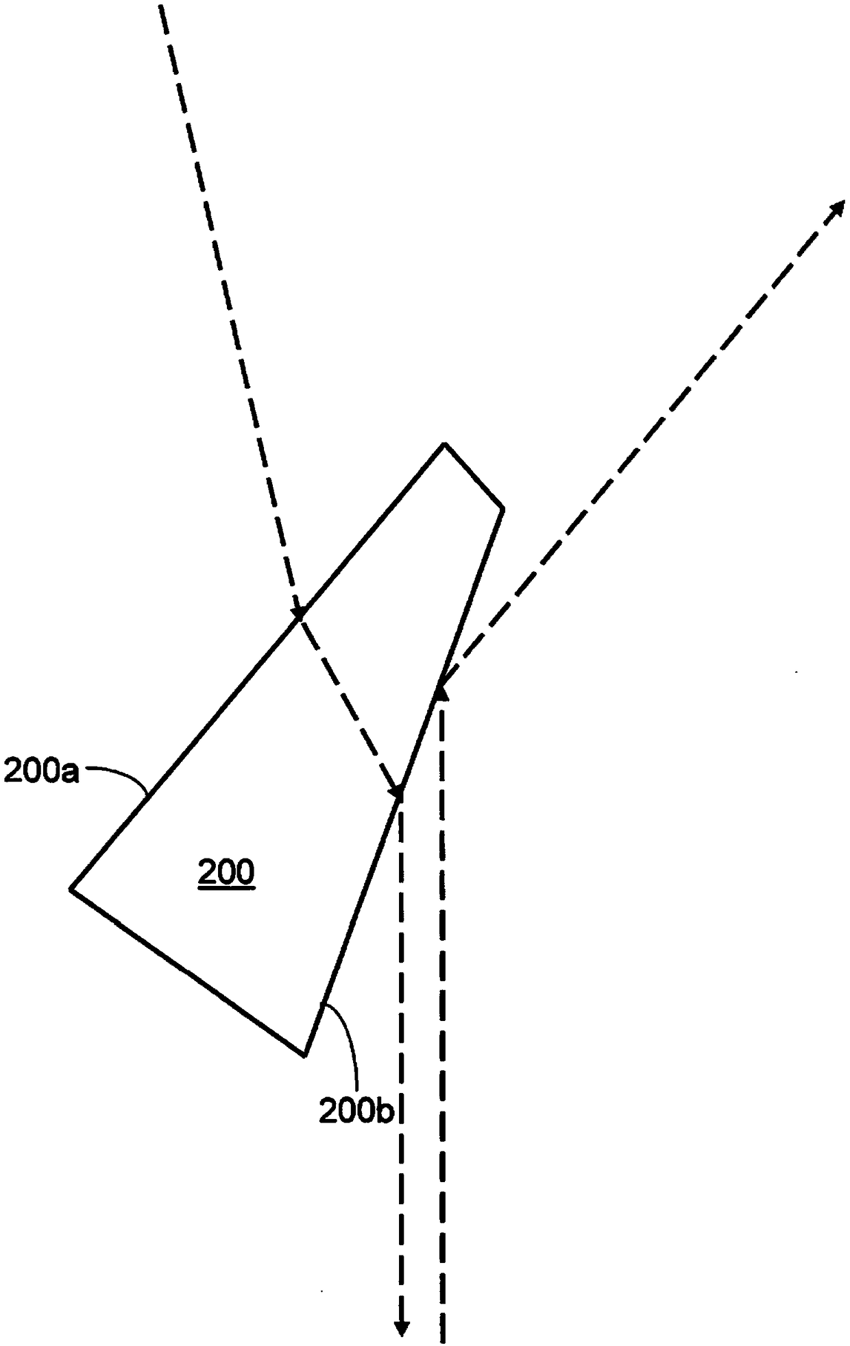
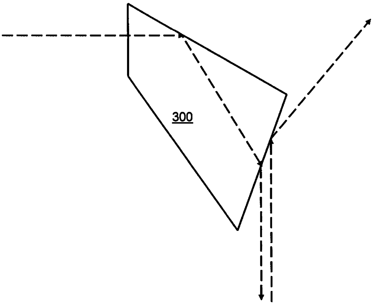
The invention relates to an optical system, particularly for microscopy, comprising a beamsplitter (100, 200, 300, 400, 500, 600, 700, 800, 900) that has a light inlet surface and a light outlet surface, wherein for a predetermined working waveband of the optical system, the beamsplitter absorbs, to less than 20%, electromagnetic radiation incident on the light inlet surface, and the beamsplitteris arranged in the optical system such that the angles of incidence relative to the respective surface normals and incident on the light inlet surface and/or the light outlet surface when the opticalsystem is in operation, are at least 70 degrees.

Description

[0001] Cross References to Related Applications [0002] This application claims priority from German patent application DE 10 2016 203 749.8 filed on March 8, 2016. The entire content of this DE application is incorporated by reference into the text of the present application. technical field [0003] The present invention relates to optical systems, in particular optical systems for microscopy. The invention can be advantageously used in various fields of application, such as microscopy applications in the field of materials science, biology or various other fundamental research. Other possible uses of the invention are mask inspection systems for inspecting reticles or masks used in microlithography projection exposure equipment. Background technique [0004] In bright-field reflected light microscopy, the object under investigation is illuminated using a beam splitter which is inclined relative to the illumination light incident from the light source and which deflects...

Claims


Application Information

Patent Timeline
Patent Type & Authority Applications(China)
IPC IPC(8): G02B27/12G02B21/16G02B21/00G02B5/30G03F7/00
CPCG02B5/3066G02B21/0016G02B21/16G02B27/12G02B27/126G03F1/84G03F7/7065
Inventor K.福克特
Owner CARL ZEISS SMT GMBH
Why Eureka
Try Eureka