Supercharge Your Innovation With Domain-Expert AI Agents!

Ignition circuit board and ignition device including the ignition circuit board

An ignition device and ignition circuit technology, applied in the field of pyrotechnics manufacturing, can solve problems such as inability to ignite ignition powder, waste of control chips, shortened ignition time, etc., to facilitate mass production and automated production, avoid potential safety hazards, and avoid reliability. low sex effect

Active Publication Date: 2020-06-26
南京雷芯聚力电子科技有限公司
View PDF4 Cites 0 Cited by
  • Summary
  • Abstract
  • Description
  • Claims
  • Application Information

AI Technical Summary

Problems solved by technology

[0004] The first is to weld the pin to the ignition circuit board first, and then weld the other end of the pin to the ignition bridge wire. The ignition bridge wire forms an ignition circuit through the pin and the ignition circuit board, and then dip the ignition bridge wire with medicine, The ignition device is formed by pointing or dropping medicine. When producing the ignition device in this way, the process is complicated, and it is difficult to realize batch automation production. In addition, there is no ignition structure protective cover outside the ignition bridge wire in the production ignition device, which is exposed on the printed circuit board. On the other hand, it is easy to be damaged when it is loaded into the electronic detonator shell and other subsequent production and processing processes;
[0005] Existing ignition bridge wires use metal wires with relatively thin diameters. Due to their own characteristics, the ignition device has the following disadvantages: the welding method of ignition bridge wires is improper, resulting in false welding of ignition bridge wires. In addition, during the welding process, due to high temperature and The pressure will also cause the ignition bridge wire in the heat-affected zone of the solder joint to shrink, the diameter will become thinner, and even cracks will occur; when the ignition device is vibrated, the ignition powder around the ignition bridge wire will move relatively, and the ignition bridge wire will deform, and some The diameter of the ignition bridge wire becomes thinner, and the resistance of the ignition bridge wire is uneven, which makes the safety current of the ignition device smaller, the ignition time is shortened, the ignition current is reduced, and its ability to resist stray current is reduced. , the temperature rises quickly, and when the ignition powder does not reach the heat required for the reaction, it will be fused, and the power supply will be cut off, resulting in the inability to ignite the ignition powder, which will affect the ignition effect of the ignition device;
[0006] In order to solve the defects of the ignition bridge wire, chip resistors are used to replace the traditional ignition bridge wire, but the shape and structure of the existing ignition circuit board cannot better meet the needs of automated mass production, and when the ignition circuit board is connected When the solder joint of the chip resistor is damaged, the ignition circuit board can only be replaced with a new one. Since the control chip has been welded on the ignition circuit board, the control chip cannot be removed and reused, resulting in waste of the control chip; at the same time, because there is no ignition structure protection The cover is easy to fall off after applying or dipping in the drug, and there is a danger of stray currents such as static electricity detonating the ignition powder, and the stability and reliability are poor;
[0007] The second is to weld the pin to the ignition circuit board first, and then weld the other end of the pin to the traditional rigid tip, so that the ignition bridge wire forms an ignition circuit through the rigid tip and the pin and the ignition circuit board. The disadvantage is that the welding of the pin and the traditional rigid tip often adopts the method of energy storage welding. Since a certain amount of current may be generated on the rigid tip during energy storage welding, there is a possibility of detonating the tip during welding. Introduced safety hazards in the production process

Method used


Image

  • Ignition circuit board and ignition device including the ignition circuit board
  • Ignition circuit board and ignition device including the ignition circuit board
  • Ignition circuit board and ignition device including the ignition circuit board

Examples


Embodiment Construction

[0027] The following will clearly and completely describe the technical solutions in the embodiments of the present invention with reference to the accompanying drawings in the embodiments of the present invention. Obviously, the described embodiments are only some, not all, embodiments of the present invention. Based on the embodiments of the present invention, all other embodiments obtained by persons of ordinary skill in the art without making creative efforts belong to the protection scope of the present invention.

[0028] In the present invention, for the convenience of description, the description of the relative positional relationship of each component is described according to the layout of the drawings in the specification, such as: the positional relationship of front, rear, left, right, etc. is based on the drawings in the specification determined by the layout direction.

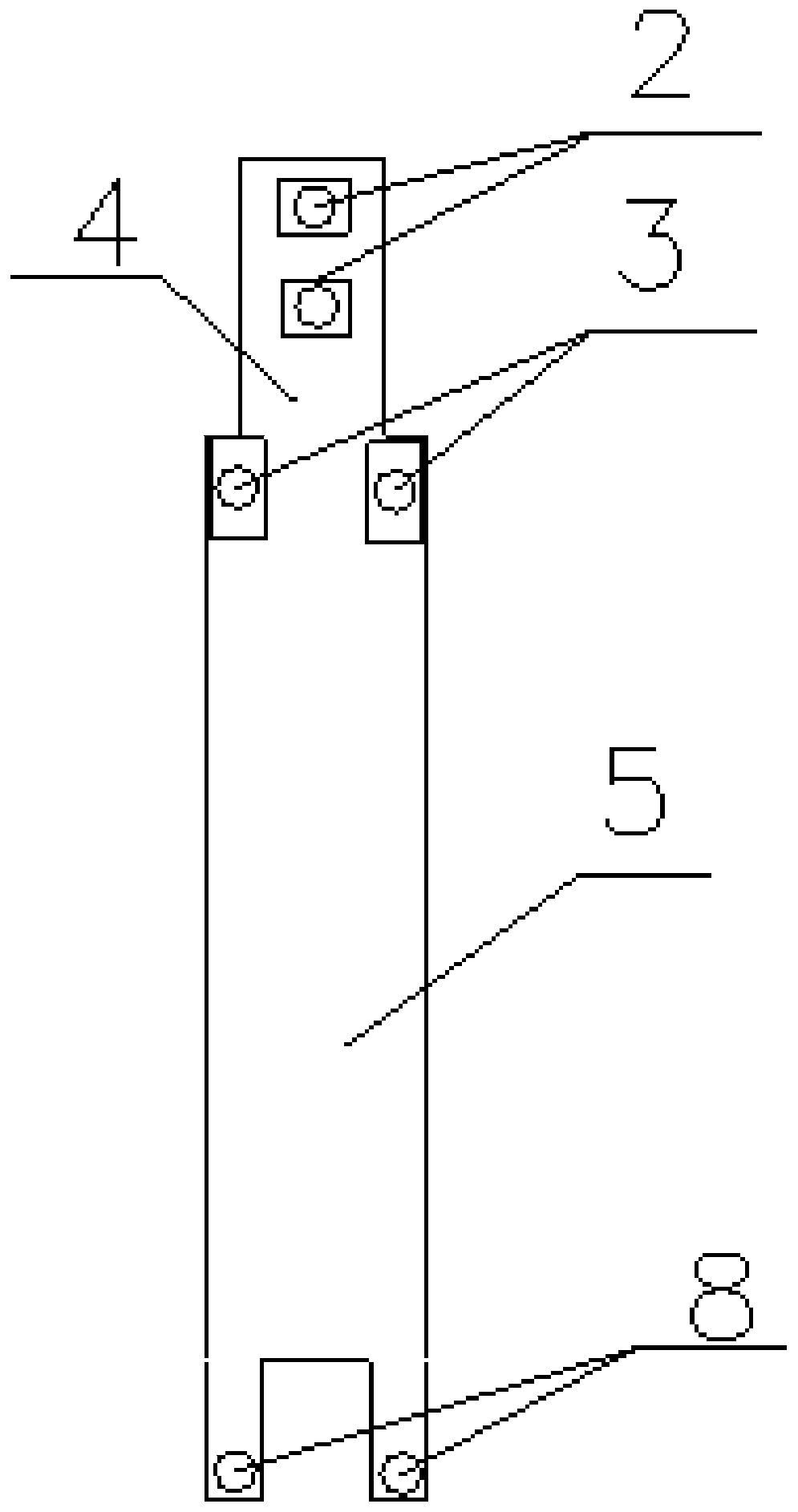
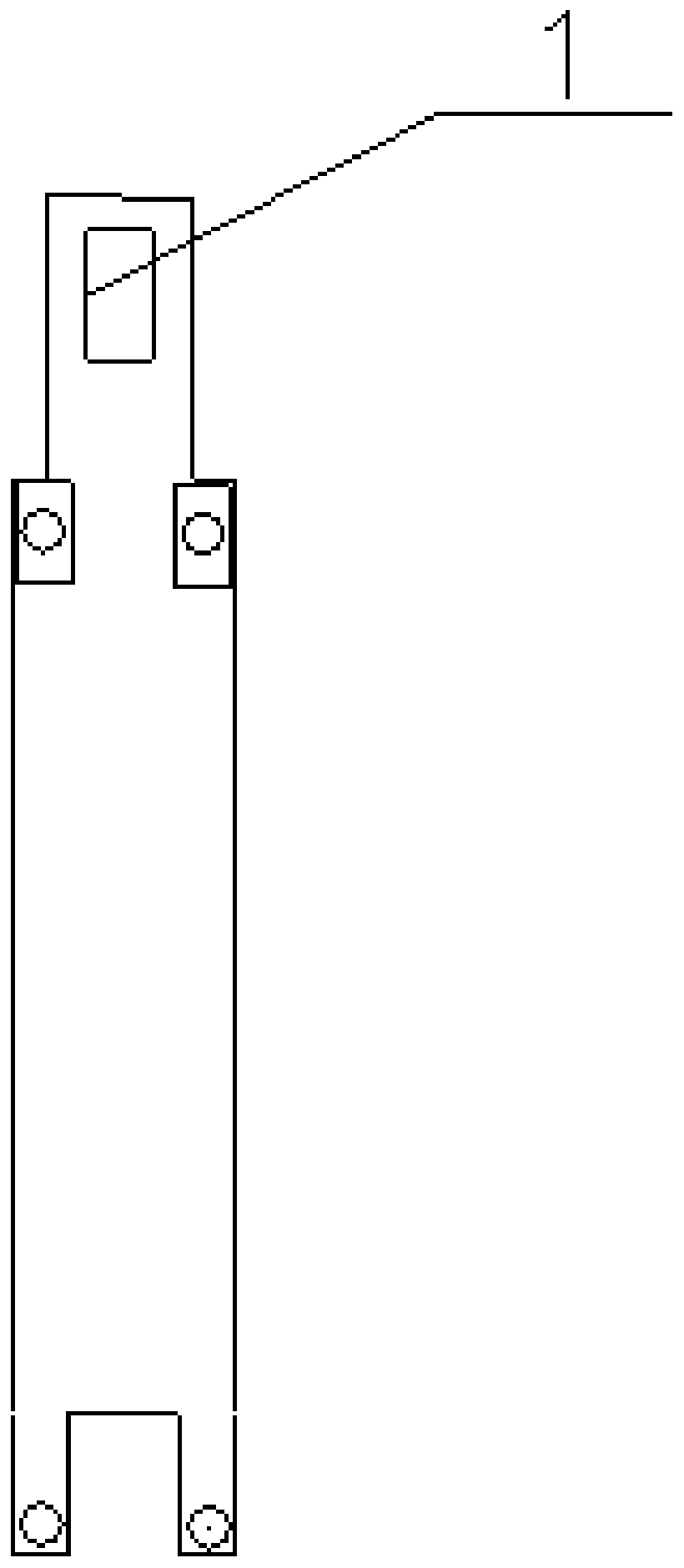
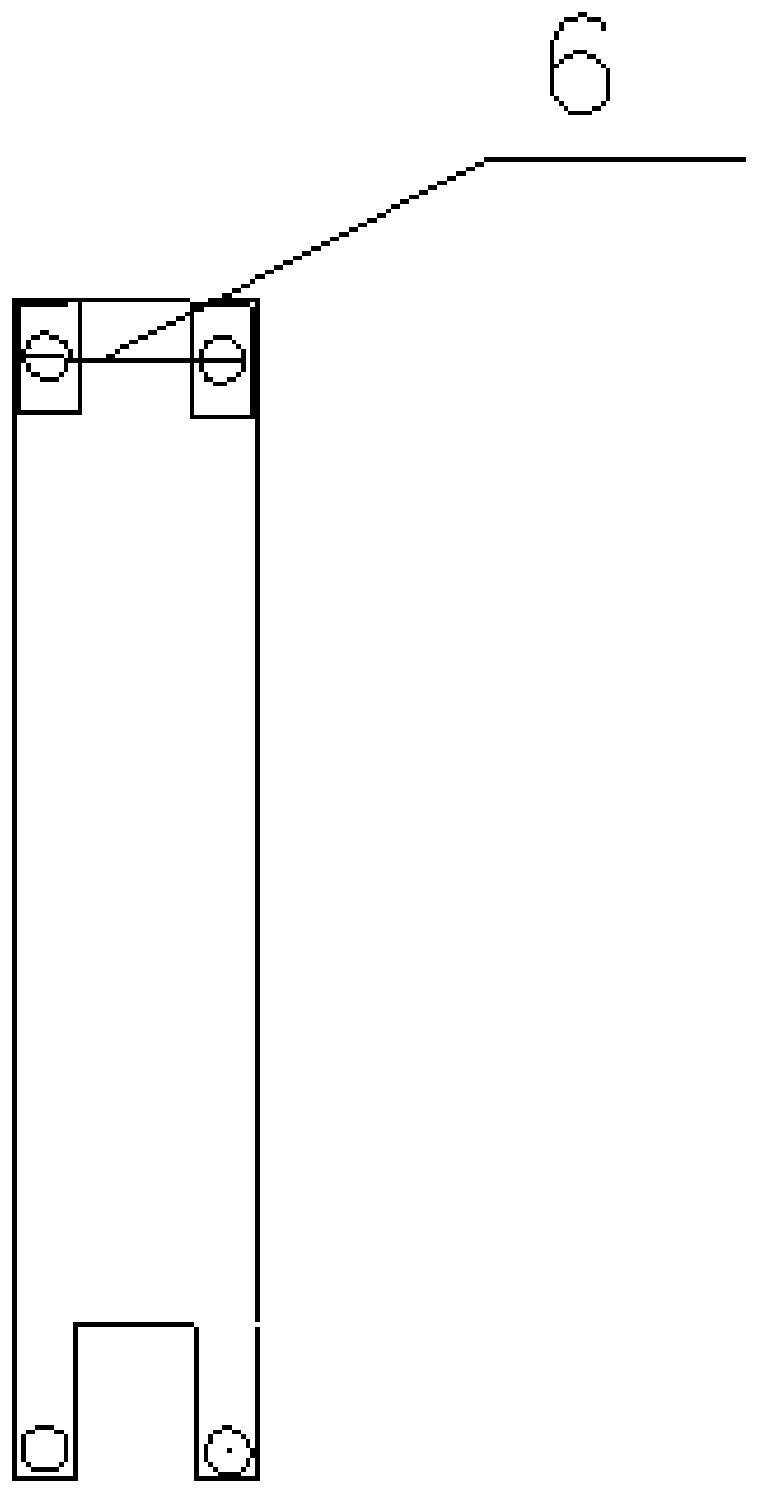
[0029] see Figure 1-5 , the present invention provides a technical solution:

[0030]An ...


PUM


Abstract

The invention relates to the technical field of initiating explosive devices, in particular to an ignition circuit board. The ignition circuit board comprises a protruding structure and a basic structure, two energy output bonding pads are arranged on the protruding structure, and two standby energy output bonding pads and a control chip are arranged on the basic structure. According to the ignition circuit board, batch and automatic production of ignition circuit boards are facilitated through the structure, the standby energy output bonding pads are arranged on the basic structure, so that when the energy output bonding pads are damaged, the standby energy output bonding pads can be directly used for being connected with a patch resistor, an ignition loop is formed, and the situation ofresource waste for the control chip installed on the printed circuit board due to replacing with a new ignition circuit board is avoided; after the ignition loop is formed, an ignition powder wraps the outer side of the patch resistor, and due to the fact that no ignition powder is generated in the welding process, the problem of potential safety hazards can be avoided from the source; and a protective film and an ignition structure protective cover are arranged on the outer side of the patch resistor so that the situation that the ignition powder falls due to the fact that people touch the ignition powder or static electricity on human body and other stray currents detonate the ignition powder can be effectively avoided, and then an ignition device is safer and more reliable.

Description

technical field [0001] The invention relates to the technical field of pyrotechnics manufacture, in particular to an ignition circuit board and an ignition device including the ignition circuit board. Background technique [0002] Electronic detonators, also known as digital electronic detonators, digital detonators or industrial digital electronic detonators, are electric detonators that use electronic control modules to control the detonation process. Electronic detonator users are still generally concerned about safety issues. [0003] In the existing electronic detonator production process, there are two commonly used manufacturing methods for ignition devices: [0004] The first is to weld the pin to the ignition circuit board first, and then weld the other end of the pin to the ignition bridge wire. The ignition bridge wire forms an ignition circuit through the pin and the ignition circuit board, and then dip the ignition bridge wire with medicine, The ignition devic...

Claims


Application Information

Patent Timeline
Patent Type & Authority Patents(China)
IPC IPC(8): F42C19/08
CPCF42C19/0823
Inventor 马文祥
Owner 南京雷芯聚力电子科技有限公司
Features
  • R&D
  • Intellectual Property
  • Life Sciences
  • Materials
  • Tech Scout
  • Unparalleled Data Quality
  • Higher Quality Content
  • 60% Fewer Hallucinations
Learn More