Experimental device for testing law of steam condensation in heavy oil reservoir conditions and operation method and application of experimental device

An experimental device and technology for heavy oil reservoirs, applied in the field of thermal recovery and development of heavy oil reservoirs, can solve problems such as complex condensation heat transfer, large differences in heat transfer characteristics, difficult steam condensation rules, etc., and achieve the effect of improving accuracy

Active Publication Date: 2018-10-30
CHINA UNIV OF PETROLEUM (EAST CHINA)
View PDF5 Cites 2 Cited by
  • Summary
  • Abstract
  • Description
  • Claims
  • Application Information

AI Technical Summary

Problems solved by technology

Heavy oil reservoir characteristics, steam injection development methods, additives and other factors will affect the steam condensation law, so there is no experimental device to test the steam condensation law under heavy oil reservoir conditions
[0005] In "Special Oil and Gas Reservoirs" 2018, Wang Yiping published an article "Nitrogen-Assisted Steam Flooding Enhanced Heat Transfer Mechanism and Causes". Condensation heat transfer in oil reservoirs is more complicated. First, the solid surface contacted by steam is core sand grains. Sand grains are composed of rock minerals, and their heat transfer characteristics are quite different from those of brass blocks. In addition, there are porous media between sand grains. Fluids such as saturated heavy oil and formation water in porous media are also quite different from brass blocks, and the pressure and temperature are relatively high under reservoir conditions. The experimental devices and methods in "Discussion on the Cause of Formation" are difficult to be used to test the law of steam condensation under the conditions of heavy oil reservoirs

Method used


Image

  • Experimental device for testing law of steam condensation in heavy oil reservoir conditions and operation method and application of experimental device
  • Experimental device for testing law of steam condensation in heavy oil reservoir conditions and operation method and application of experimental device
  • Experimental device for testing law of steam condensation in heavy oil reservoir conditions and operation method and application of experimental device

Examples


Embodiment 1

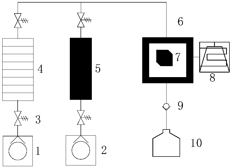
[0058] Such as figure 1 , 3 shown.

[0059] An experimental device for testing the law of steam condensation under the conditions of heavy oil reservoirs, comprising steam generation injection pipelines, injection pipelines for auxiliary production fluids, and a condensation chamber; the auxiliary production fluids are: nitrogen, carbon dioxide, flue gas, Viscosity solution or foaming agent solution etc.; In the present embodiment 1, only inject steam to described condensing chamber;

[0060] The steam generation injection pipeline and the injection pipeline of the auxiliary production fluid are respectively connected with the condensation chamber;

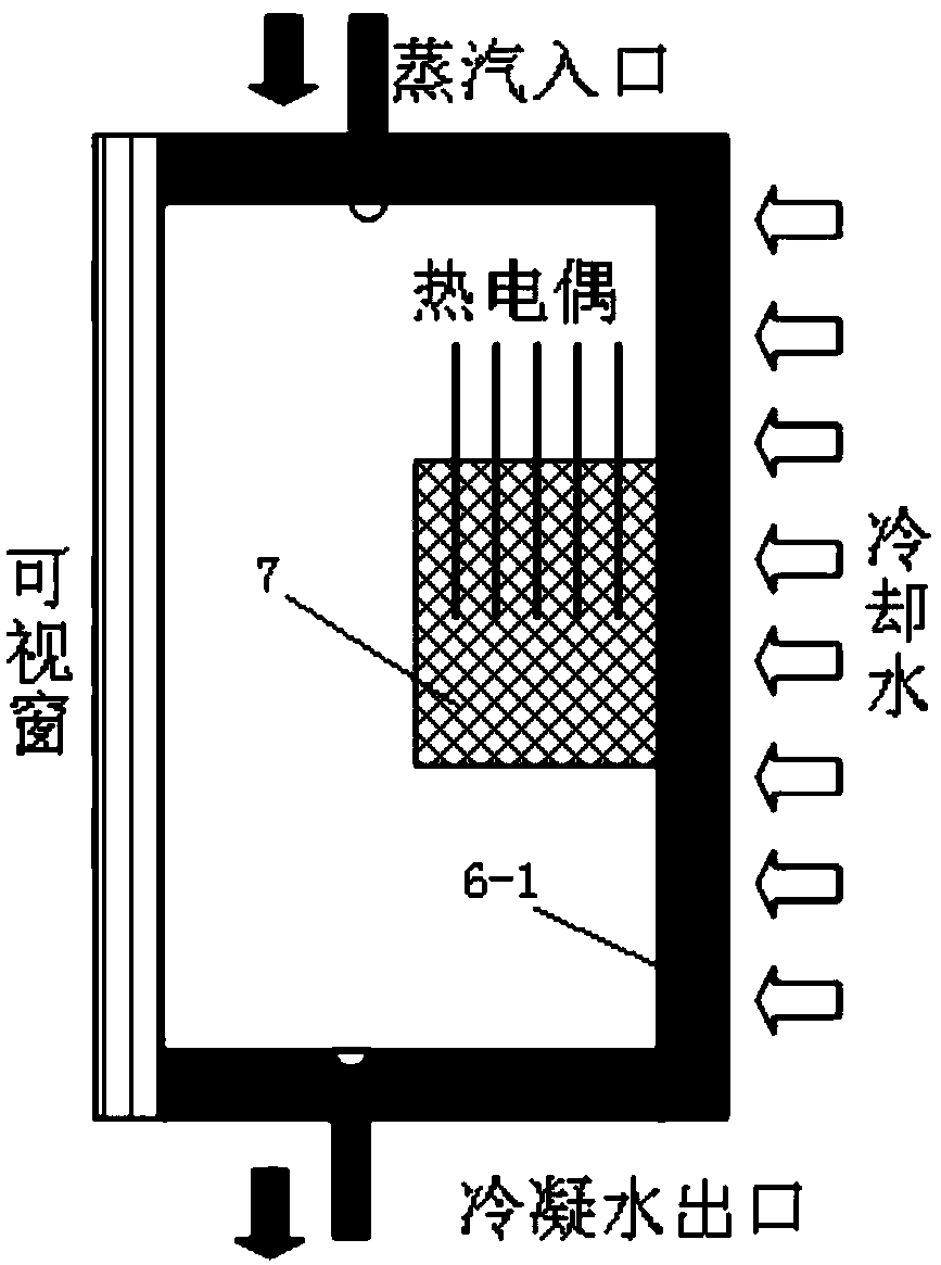
[0061] The condensation chamber includes a condensation installation wall, an observation window arranged opposite to the condensation installation wall, and a condensate collection channel is arranged at the bottom of the condensation chamber;

[0062] The steam generation injection pipeline and the injection pipeline of the a...

Embodiment 2

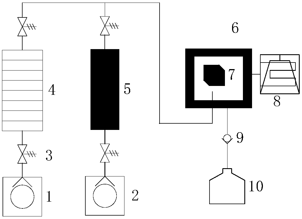
[0069] Such as figure 2 , 4 shown.

[0070] An experimental device for testing the law of steam condensation under the conditions of heavy oil reservoirs as described in Example 1, the difference is that the injection pipeline communicates with the bottom end of the condensation chamber 6, wherein the steam injection end It is placed under the end face of the experimental rock core 7, and the distance from the lower end face of the experimental rock core is 3 mm. The invention is designed to be connected from the bottom, and the steam is injected from the lower part and then contacts the experimental rock core to simulate the condensation phenomenon after the steam contacts the rock core in the development process of steam assisted gravity drainage (SAGD).

[0071] In the present invention, the high-precision plunger pump of the ISCO pump is used to respectively inject steam condensed steam and auxiliary production fluid into the condensation chamber through the steam gener...

Embodiment 3

[0073] The working method of experimental device as described in embodiment 1, comprises:

[0074] Installation before the experiment: Select the experimental core according to the heavy oil formation environment to be simulated and saturate the formation water and heavy oil, wherein the experimental core is an underground core core of a heavy oil reservoir, and then cut the core core by a core cutting machine Become a square experimental core 7 of 20mm×20mm×24mm; vacuumize the experimental core 7, saturate the formation water, measure the permeability, and the permeability is 1.5μm 2 , is saturated with heavy oil in the target reservoir, and the initial oil saturation is 0.65;

[0075] The above-mentioned treated experimental core is installed on the condensation installation wall of the condensation chamber, and a plurality of temperature sensors are distributed in the experimental core to monitor the temperature distribution and temperature change of the experimental core d...


PUM

PropertyMeasurementUnit
viscosityaaaaaaaaaa

Abstract

The invention discloses an experimental device for testing the law of stream condensation in heavy oil reservoir conditions. The experimental device comprises a steam generation filling pipeline, a filling pipeline for auxiliary production fluid and a condensation chamber; the steam generation filling pipeline and the filling pipeline for the auxiliary production fluid are respectively connected with the condensation chamber; the steam generation filling pipeline and the filling pipeline for the auxiliary production fluid are parallelly connected into the filling pipeline to be connected withthe condensation chamber; an experimental core with saturated formation water and heavy oil is arranged on the condensation installation wall. The experimental core is controlled by the interference of external temperature on the condensing mounting wall, which is consistent with the simulated actual formation core temperature; meanwhile, the temperature and pressure in a condensing chamber are controlled to stimulate real environmental conditions and parameters in actual strata; finally according to requirements of experimental research, steam is injected into the condensing chamber alone ormixed with steam and one or more auxiliary production fluids, and a variety of experimental comparison of technical results is achieved.

Description

technical field [0001] The invention relates to an experimental device for testing the law of steam condensation under heavy oil reservoir conditions, its working method and application, and belongs to the technical field of thermal recovery and development of heavy oil reservoirs. Background technique [0002] Heavy oil is crude oil with high asphaltene and colloid content and high viscosity. The viscosity of degassed crude oil is greater than 100mPa.s at the original reservoir temperature. my country's heavy oil resources are widely distributed. Onshore heavy oil resources account for more than 20% of the total oil resources. The proven geological resources are 7.98 billion tons, and the annual output exceeds 28 million tons, accounting for 14% of domestic crude oil production. An important part of my country's crude oil production. Further increasing heavy oil production is an important guarantee for maintaining the stability of China's oil production and maintaining nati...

Claims


Application Information

Patent Timeline
Patent Type & Authority Applications(China)
IPC IPC(8): G01N25/14
CPCG01N25/142
Inventor 鹿腾李兆敏王壮壮徐正晓徐亚杰
Owner CHINA UNIV OF PETROLEUM (EAST CHINA)
Why Eureka
Try Eureka