Dual-band dual-polarized electromagnetic band gap structure

An electromagnetic bandgap structure, dual polarization technology, applied in the direction of circuit, electrical components, antenna coupling, etc., can solve the problems of small range, narrow, increased EBG thickness, etc.

Active Publication Date: 2018-10-30
UNIV OF ELECTRONICS SCI & TECH OF CHINA
View PDF7 Cites 6 Cited by
  • Summary
  • Abstract
  • Description
  • Claims
  • Application Information

AI Technical Summary

Problems solved by technology

Mushroom-type EBG can provide a wide "surface wave suppression" bandwidth and "in-phase reflection" bandwidth, but in general, the existence of metal vias makes the structure processing complicated, so some planar EBG structures have been proposed. There is no metal via, but there is a disadvantage of planar EBG. The "surface wave suppression" bandwidth and the "in-phase reflection" bandwidth cannot be very wide at the same time. The reason is that in order to obtain a wider "surface wave suppression" bandwidth, it is necessary to use Thinner dielectric substrate, however thinner dielectric substrate reduces "in-phase reflection" bandwidth
On the contrary, increasing the thickness of the dielectric substrate can obtain a wider "in-phase reflection" bandwidth, but the "surface wave suppression" bandwidth will become narrower
[0004] Most traditional EBG structures work on a single frequency band. In order to obtain dual-band characteristics, cascaded periodic arrays can be used, but the use of multi-layer structures will increase the thickness of EBG
Although some single-layer concentric arrays can also have dual-frequency characteristics, the adjustable range of the frequency ratio (the frequency ratio between the high-frequency bandgap and the low-frequency bandgap) is very small
The EBG structure proposed in the literature "Perturbed frequency selective surfaces for multiband high impedance surfaces." has a wide frequency ratio adjustment range, but this structure only exhibits single polarization characteristics

Method used


Image

  • Dual-band dual-polarized electromagnetic band gap structure
  • Dual-band dual-polarized electromagnetic band gap structure
  • Dual-band dual-polarized electromagnetic band gap structure

Examples


Embodiment Construction

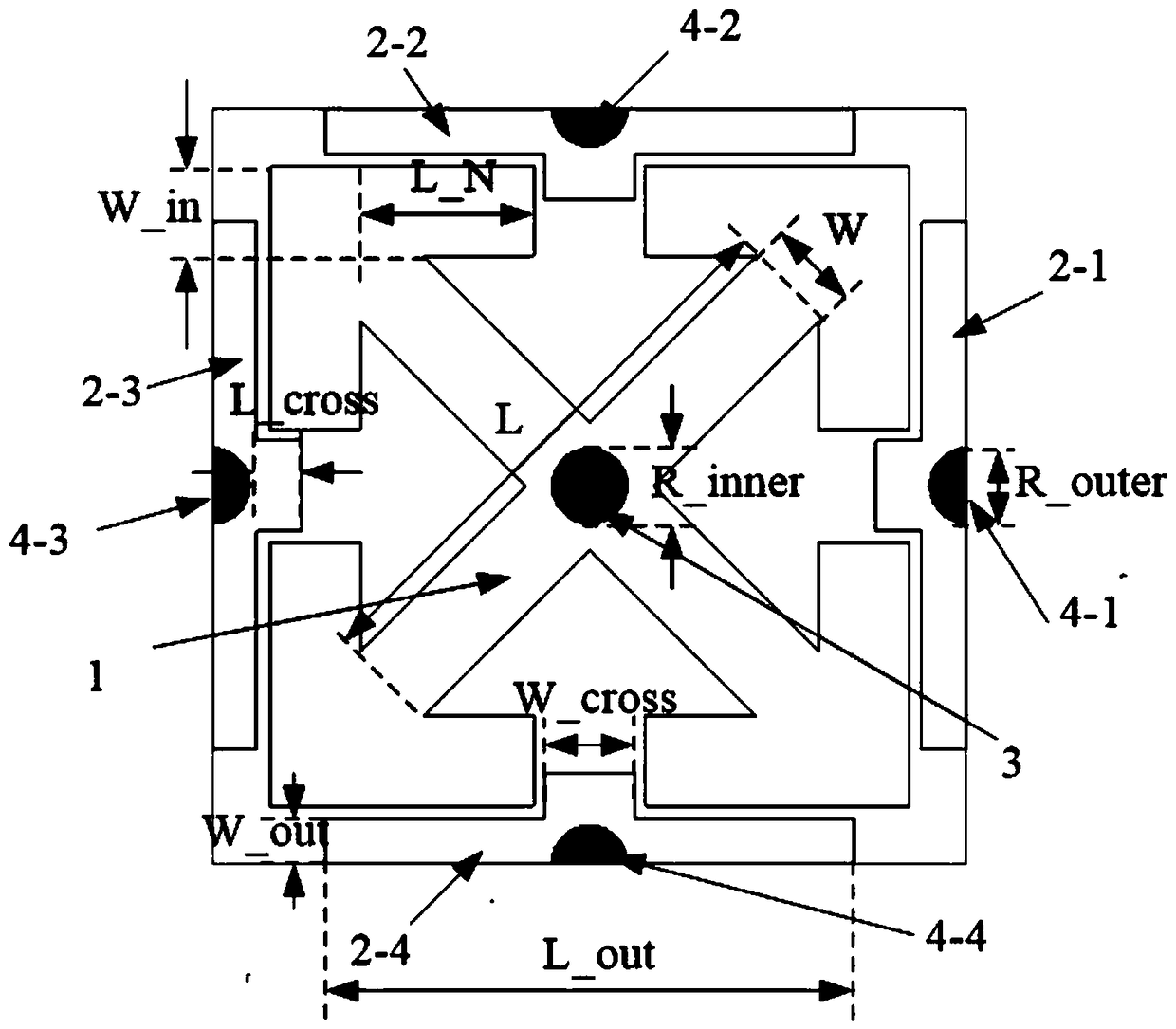
[0014] The dual-frequency dual-polarization electromagnetic bandgap structure of this embodiment is composed of internal "Jerusalem" cross-shaped cells and external T-shaped cells, and the internal and external cells are connected to the metal floor through metal vias. The "Jerusalem" cross cell resonates at low frequencies, while the T cell resonates at high frequencies.

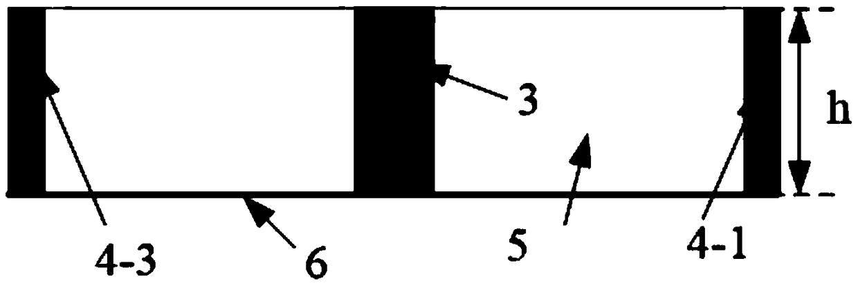
[0015] Such as figure 1 , 2 It is a schematic diagram of an embodiment of the present invention, and the entire structure is symmetrical about the center. Including the dielectric substrate 5, the modified "Jerusalem" cross-type cell 1 printed on the center of the front of the dielectric substrate 5, the "Jerusalem" cross-type cell 1 is rotated by 45° from the traditional "Jerusalem" structure, and its outer branches pass through the inward After folding, it presents a 90° "L"-shaped structure, and the two arms of the "L"-shaped structure are of the same size. A metal cylindrical via hole 3 is also provi...


PUM


Abstract

The invention discloses a dual-band dual-polarized electromagnetic band gap structure, belonging to the field of wireless communication. The electromagnetic band gap structure comprises a medium substrate, a metal floor arranged on the back of the medium substrate, a variant 'Jerusalem' cross-type cell arranged on the front of the medium substrate, and four T-type cells. The dual-band dual-polarized electromagnetic band gap structure can be widely used in the field of wireless communication, can be used for designing dual-band dual-polarized antennas to improve the performance of the antennas.The dual-band dual-polarized electromagnetic band gap structure has both two 'in-phase reflection phase' bands and two 'surface wave suppression' bands, has a wider band ratio adjustment range and iscompact.

Description

technical field [0001] The invention belongs to the field of wireless communication, in particular to a compact dual-frequency dual-polarization electromagnetic bandgap structure. Background technique [0002] Electromagnetic Band-Gap (EBG) has been extensively studied in the past few decades. It has two important properties, namely: "suppression of surface waves" and "in-phase reflection" characteristics. Among them, the "surface wave suppression" feature can improve the performance of the antenna array by reducing the mutual coupling between the antenna elements. The "in-phase reflection" feature can be used in the design of low-profile antennas as well as broadband antennas. [0003] The most common is the mushroom-type EBG, which is printed on a dielectric substrate with a metal ground on the back by a periodic metal patch array, and the metal patch and the metal ground are connected through metal vias. Mushroom-type EBG can provide a wide "surface wave suppression" b...

Claims


Application Information

Patent Timeline
Patent Type & Authority Applications(China)
IPC IPC(8): H01Q1/52H01Q15/00
CPCH01Q1/523H01Q15/0013
Inventor 孟凡计王玉文刘影李泽坤
Owner UNIV OF ELECTRONICS SCI & TECH OF CHINA
Why Eureka
Try Eureka