
A welding process method for mechanical seal components

A technology of mechanical sealing and process method, which is applied in welding equipment, manufacturing tools, welding equipment, etc., can solve the problems of small mechanical bonding force, poor thermal and electrical conductivity, and low effective bonding rate, and achieve strong mechanical bonding force and thickness Uniform and effective bonding effect with high rate

Active Publication Date: 2020-06-02
CHENGDU ZHONGCHAO CARBON SCI & TECH
View PDF6 Cites 0 Cited by
  • Summary
  • Abstract
  • Description
  • Claims
  • Application Information

AI Technical Summary

Problems solved by technology

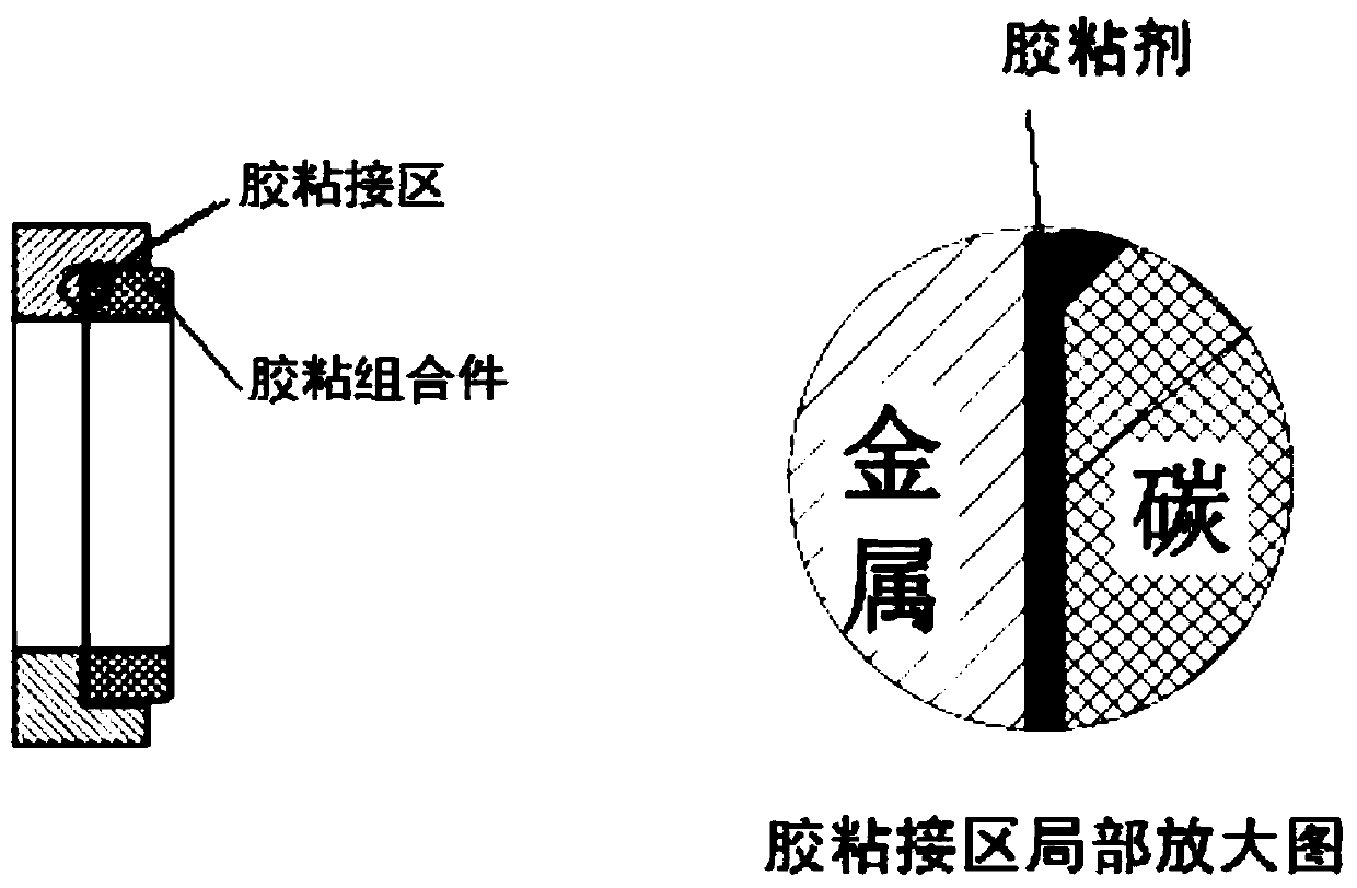
[0006] Another purpose of the present invention is to solve technical problems such as low effective lamination rate, small mechanical bonding force, and poor thermal and electrical conductivity of the bonding surface between the carbon ring and the metal base in the mechanical seal prepared by the existing process.

Method used


Image

  • A welding process method for mechanical seal components
  • A welding process method for mechanical seal components
  • A welding process method for mechanical seal components

Examples


Embodiment 1

[0030] A welding process method for a mechanical seal assembly, comprising the following steps:

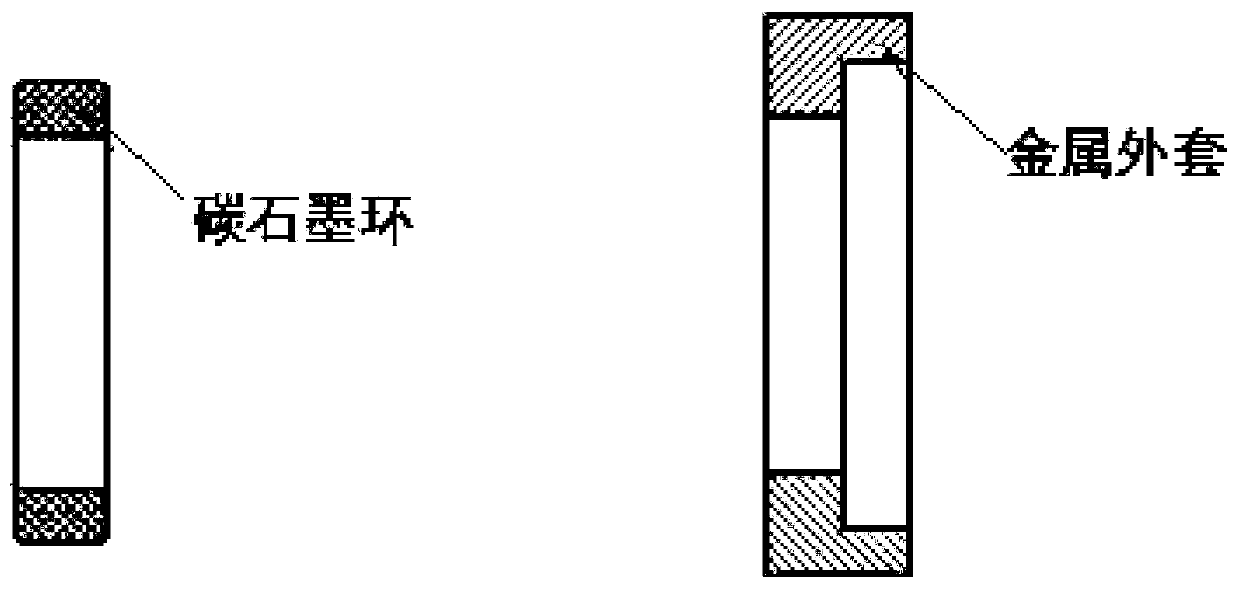
[0031] S1. Processing and forming carbon rings. The outer circle of the carbon ring is processed in place at one time, and processed to the target size. The inner circle and total length of the carbon ring leave a margin of 3-5mm for subsequent finishing. The carbon ring One end chamfer of the outer circle is 0.5*45°. A circular metal base matched with the carbon ring is processed and formed, and an annular accommodation groove for accommodating the carbon ring is provided on the inner side of the metal base.

[0032] S2. Carbon ring pretreatment: first put the processed carbon ring into the cleaning solution and soak it, then ultrasonically clean it, and finally rinse it with water until there is no dust on the surface of the carbon ring; then dry the cleaned carbon ring Dry.

[0033] S3. Electroplating a metal nickel film or zinc film with a thickness of 0.1 mm on the outer su...

Embodiment 2

[0037] A welding process method for a mechanical seal assembly, comprising the following steps:

[0038] S1. Processing and forming carbon graphite ring, the outer circle of carbon graphite ring is processed in place at one time, processed to the target size, one end face chamfer of the outer circle is 0.5*45°, and the inner circle and total length of carbon graphite ring are left with 3 ~ 5mm Surplus for subsequent finishing. A circular metal base matched with the carbon-graphite ring is processed and formed, and an annular accommodation groove for accommodating the carbon-graphite ring is provided on the inner side of the metal base.

[0039] S2. Carbon-graphite ring pretreatment: first, soak the processed carbon-graphite ring in the cleaning solution, then ultrasonically clean it, and finally rinse with water until the surface of the carbon-graphite ring is free of dust; then put the cleaned carbon-graphite ring on the Dry at a temperature not exceeding 200°C.

[0040] S3...


PUM

PropertyMeasurementUnit
thicknessaaaaaaaaaa

Abstract

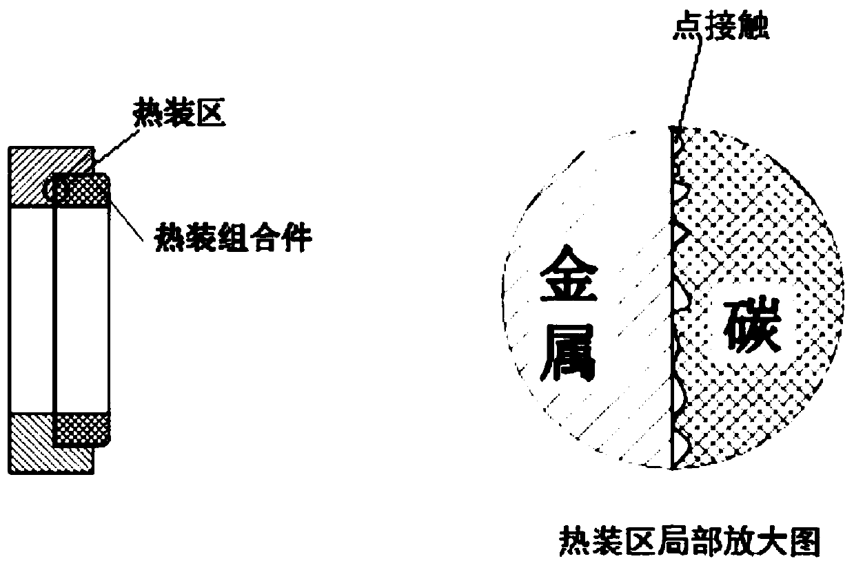
The invention discloses a welding process method of a mechanical sealing assembly. The welding process method of the mechanical sealing assembly comprises the following steps that S1, a carbon circular ring and a matched metal base are machined and molded separately; S2, the carbon circular ring is subjected to pretreatment; S3, a metal film is electroplated on the outer surface of the pretreatedcarbon circular ring through an electroplating method; S4, the metal base is heated to volume expansion, metal welding flux is put into the metal base, then the carbon circular ring obtained in the step S3 is embedded and welded into the metal base while it is hot, surplus welding flux is extruded out while the metal base shrinks in size to clamp the carbon circular ring along with decreasing of the assembly temperature, and the metal base is effectively combined with the carbon circular ring together; and S5, the inner circle and end face of the welded metal base and carbon circular ring aresubjected to finish machining, and then the mechanical sealing assembly is obtained. For the sealing assembly obtained by adopting the welding process, the contact face between the carbon circular ring and the metal base is high in fit rate, mechanical combination force is high, thermal conductivity is high, impermeability and pressure resistance are good, and the mechanical sealing overall performance can be effectively improved.

Description

technical field [0001] The invention relates to the technical field of mechanical seal assembly manufacturing, in particular to a welding process method of a mechanical seal assembly. Background technique [0002] At the end of some rotating shafts with very high operating speeds, there are more and more ways to use mechanical seals. The mechanical seal has the advantages of light weight, compact size, small space occupation, long service life, convenient installation and high reliability, which can well meet the sealing requirements of high-speed transmission components. At present, mechanical seals are mainly composed of dynamic and static ring components, see figure 1 . Since the mechanical seal friction pair needs to run at high speed during work, and at the same time bear certain pressure, temperature, and corrosive changes in the medium, the material requirements for the friction pair are as follows: 1. In terms of mechanical properties: it is required to have a high...

Claims


Application Information

Patent Timeline
Patent Type & Authority Patents(China)
IPC IPC(8): B23K37/00B23K31/02
CPCB23K31/02B23K37/00
Inventor 侯玉杰程诺
Owner CHENGDU ZHONGCHAO CARBON SCI & TECH
Learn More