

Wire bonding tool
A wire bonding tool and wire bonding head technology, which is applied in the manufacture of electrical components, electrical solid devices, semiconductor/solid devices, etc., can solve problems such as deformation and achieve excellent electrical conductivity
- Summary
- Abstract
- Description
- Claims
- Application Information
AI Technical Summary
Problems solved by technology
Method used
Image

Examples
no. 1 example
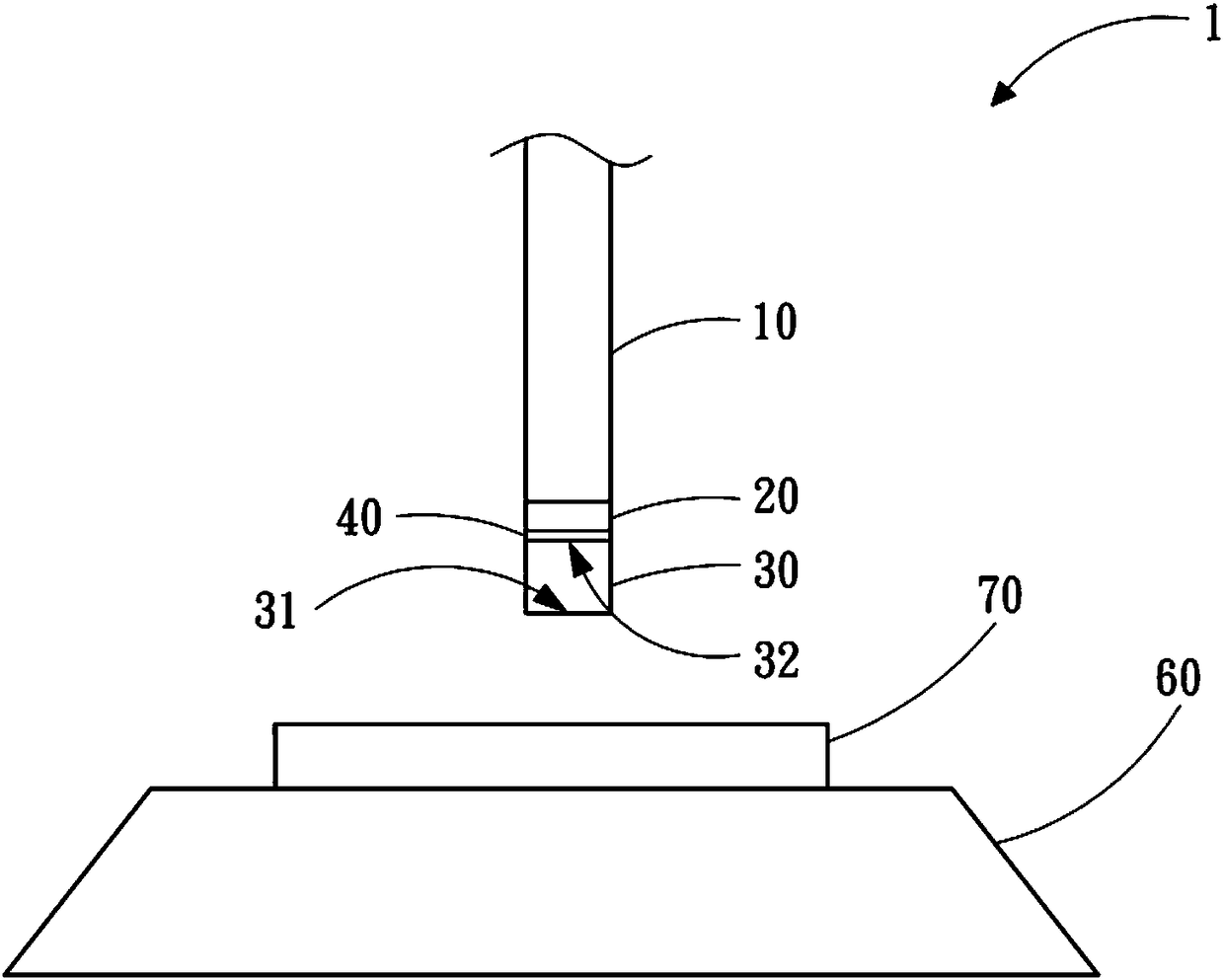
[0032] " figure 1 』is a structural schematic diagram of the wire bonding tool 1 according to the first embodiment of the present invention, including: a working seat 10; a bonding layer 20; a bonding head 30; and a bonding layer 20 and the bonding head 30. The first diamond layer 40 . The bonding head 30 has a working surface 31 and a non-working surface 32 , and the first diamond layer 40 is formed on the non-working surface 32 .
[0033] In the wire bonding tool 1 of this embodiment, the material of the working seat 10 may include iron-nickel alloy, iron-nickel-cobalt alloy, iron-nickel-chromium alloy, iron-cobalt-chromium alloy, or any combination thereof, and specific examples include alloys of Invar or Kovar , but the present invention is not limited thereto, and other metals or alloys with low thermal expansion coefficients can also be used.
[0034] The bonding layer 20 is disposed on one side of the work seat 10 . In this embodiment, the material of the bonding laye...
no. 2 example
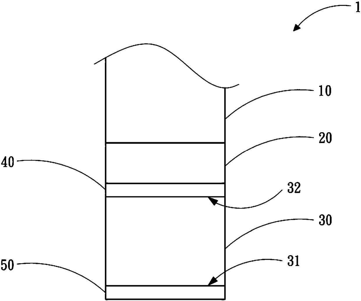
[0040] Please refer to figure 2 The wire bonding tool 1 of the second embodiment of the present invention is substantially the same in structure as the wire bonding tool 1 of the first embodiment, except that this embodiment further includes a second diamond layer 50 . The second diamond layer 50 is formed on the working surface 31 of the wire bonding head 30 by a chemical vapor deposition method and directly contacts the wire bonding head 30 .
[0041] Since the compositions, structures, and features of the work base 10 , the bonding layer 20 , the bonding head 30 , and the first diamond layer 40 of this embodiment are the same as those of the first embodiment above, no further description is given here.
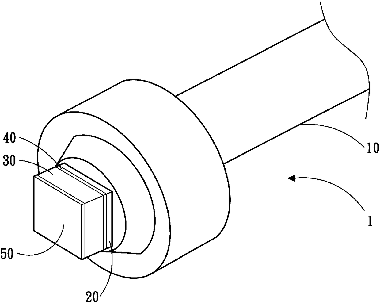
[0042] image 3 and Figure 4 It is a schematic diagram of a wire bonding tool in other embodiments of the present invention. The shape of the wire bonding head 30 can be designed and adjusted according to actual needs without any special limitation, as long as the bondi...
no. 3 example
[0044] Please refer to Figure 5 . The wire bonding tool 1 of the third embodiment of the present invention is substantially the same in structure as the wire bonding tool 1 of the second embodiment, the difference is that in this embodiment, there is also a An intermediate layer 80 .
[0045] Specifically, the wire bonding tool of the third embodiment of the present invention includes: the work seat 10; the bonding layer 20 arranged on one side of the work seat 10; The first diamond layer 40 on one side of the seat 10; the wire head 30 arranged on the side of the first diamond layer 40 away from the bonding layer 20; the wire head 30 arranged on a side away from the first diamond layer 40 The middle layer 80 on the side; and the second diamond layer 50 formed on the side of the middle layer 80 away from the wire bonding head 30 by chemical vapor deposition.
[0046] In this embodiment, the thickness of the intermediate layer 80 is between 0.1 μm and 20 μm, preferably betwe...
PUM
| Property | Measurement | Unit |
|---|---|---|
| Particle size | aaaaa | aaaaa |
| Particle size | aaaaa | aaaaa |
| Particle size | aaaaa | aaaaa |
Abstract
Description
Claims
Application Information