
Industrial waste gas treatment method

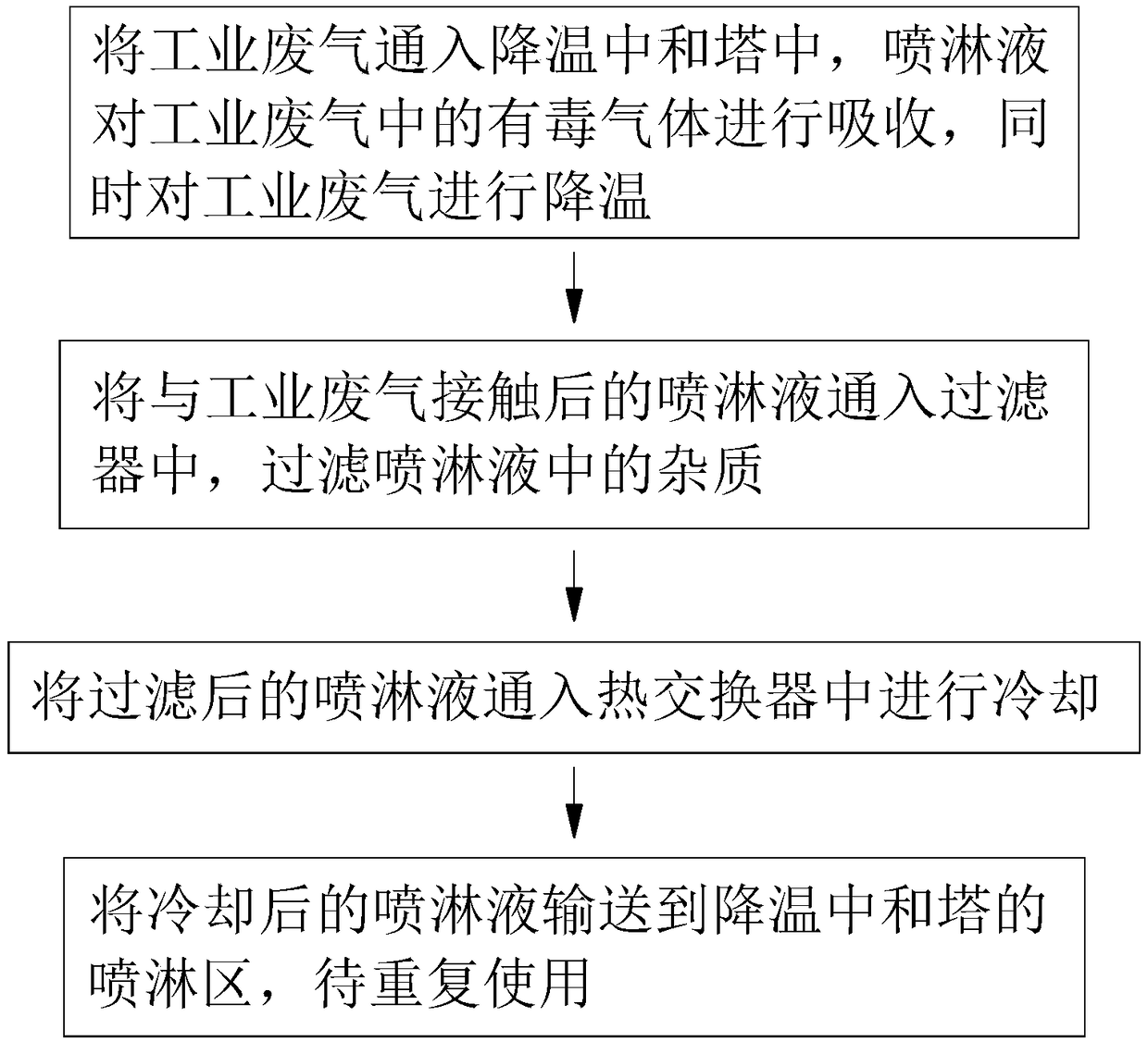
A technology for industrial waste gas and spray liquid, which is applied in gas treatment, separation methods, chemical instruments and methods, etc., can solve the problems of increased equipment cost, decreased cost performance, restrictions, etc., and achieves the effect of improving heat exchange efficiency

Pending Publication Date: 2018-11-06
李洁
View PDF8 Cites 1 Cited by
  • Summary
  • Abstract
  • Description
  • Claims
  • Application Information

AI Technical Summary

Problems solved by technology

However, for the treatment of high-temperature industrial waste gas, the absorption method is effective for the removal of pollutants, but the absorption equipment must use high-temperature-resistant and corrosion-resistant materials
The increase in equipment cost, that is, the increase in engineering investment and the decrease in cost performance, limit the application of absorption method in high-temperature waste gas treatment

Method used

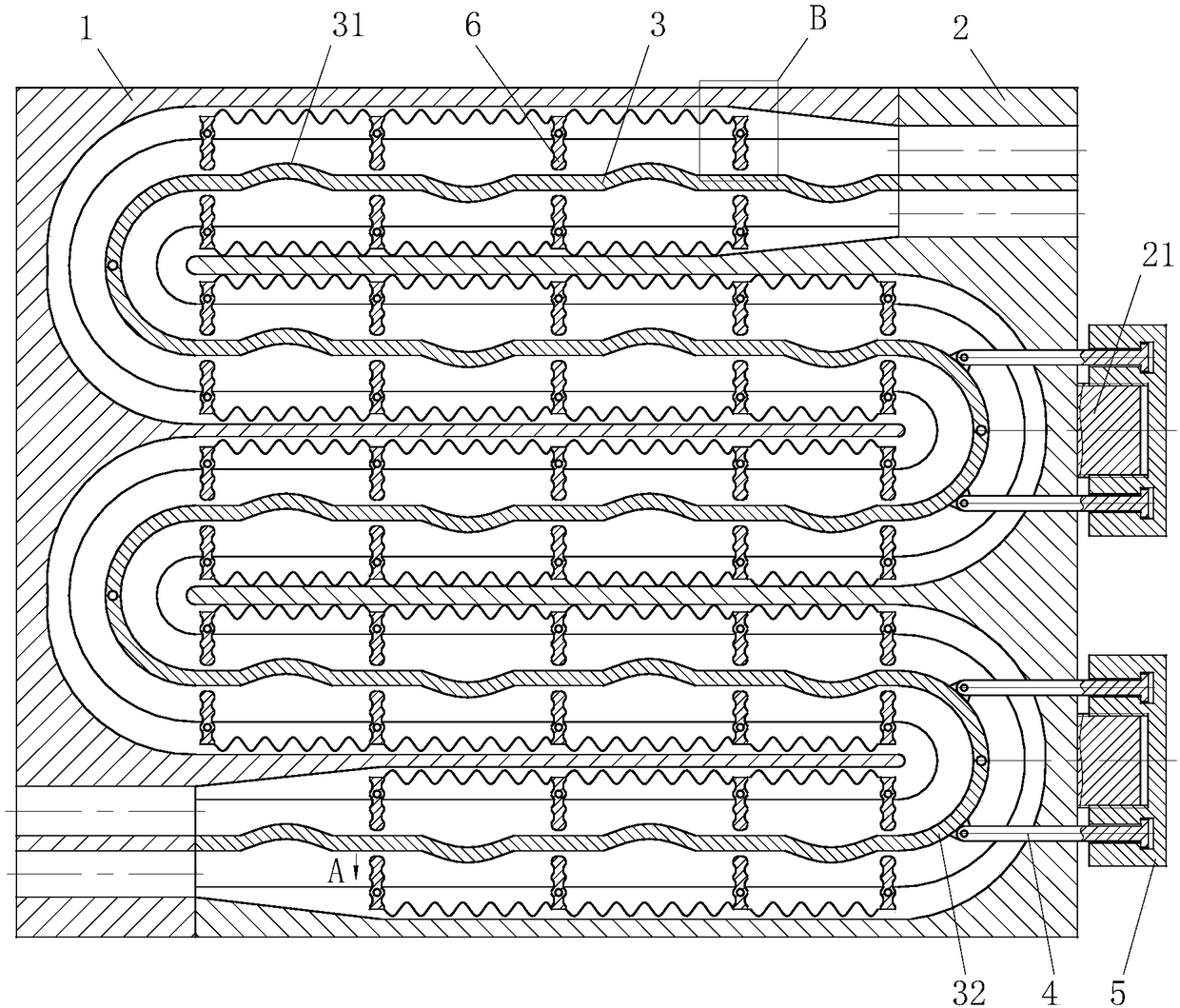
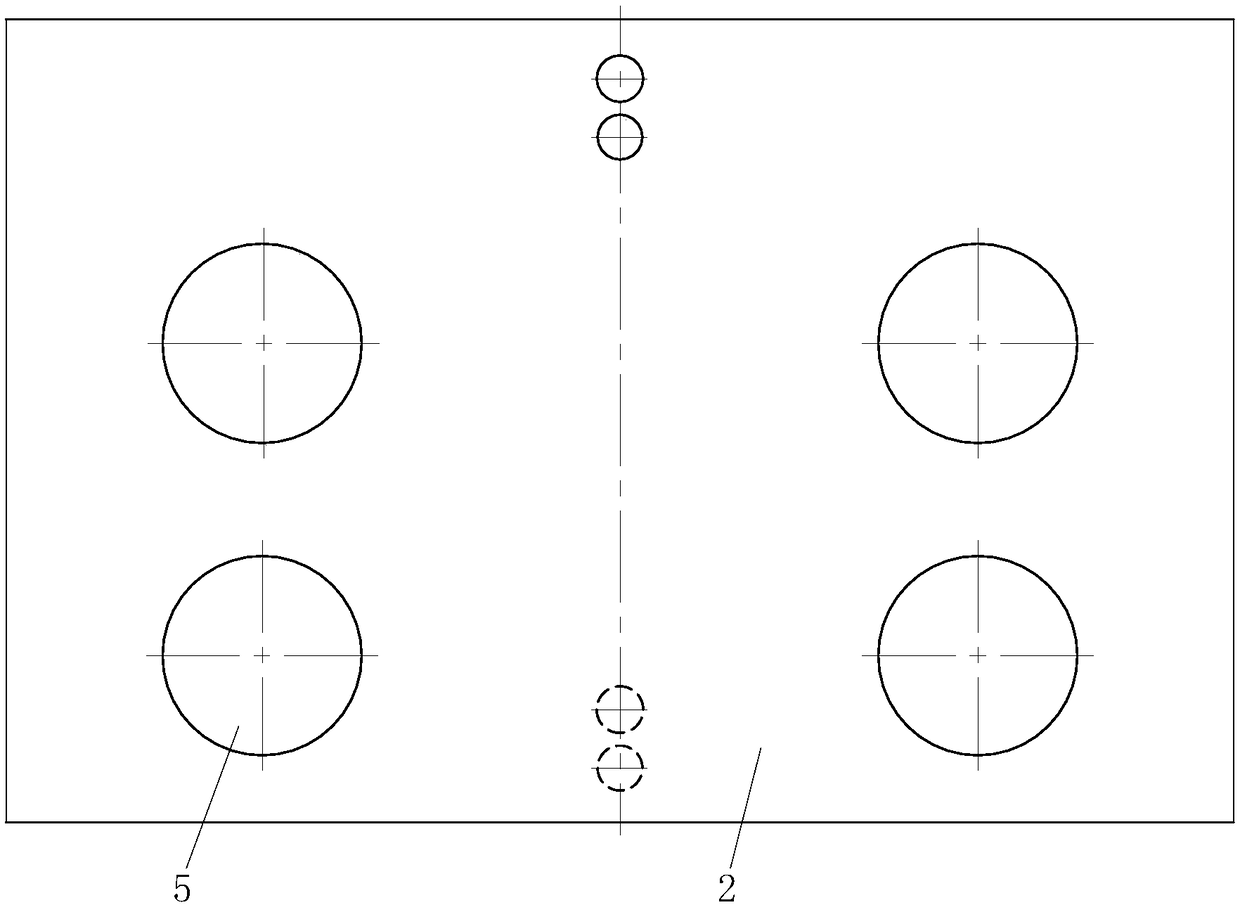

Image

  • Industrial waste gas treatment method
  • Industrial waste gas treatment method
  • Industrial waste gas treatment method

Examples


Embodiment approach

[0047] As the first embodiment of the drainage groove 33 of the present invention, the two sides of the drainage groove 33 of the swing plate 6 are provided with baffles 7 alternately at intervals; one end of the baffle 7 is fixedly connected to the side wall of the drainage groove 33; When in use, the flowing liquid overcomes the elastic force of the torsion spring and pushes the swing plate 6 to swing. The flowing liquid bypasses the baffle 7 in the drainage groove 33 on the swing plate 6 and is discharged, and the liquid is bent in the drainage groove 33 on the swing plate 6. During the flow process, heat exchange is performed through the heat exchange baffle 3, and the liquid that continuously changes the direction of movement further improves the heat exchange efficiency.

[0048] As a second embodiment of the drainage groove 33 of the present invention, sliding grooves 331 are provided on both sides of the drainage groove 33 of the swing plate 6, and the lengths of the slidi...


PUM


Abstract

The invention belongs to the technical field of waste gas treatment and particularly relates to an industrial waste gas treatment method. A heat exchanger used in the method comprises a left casing, aright casing and heat exchange partition plates, wherein the left casing and the right casing are mounted together in a mutually-staggered manner; the heat exchange partition plates are arranged in acavity formed by rectangular grooves of the left casing and rectangular grooves of the right casing; the positions of turning circular arcs at the left end of the heat exchange partition plate are hinged to the side walls of the rectangular grooves of the left casing through rotating shafts, and the positions of turning circular arcs at the right end of the heat exchange partition plate are hinged to the side walls of the rectangular grooves of the right casing through rotating shafts. The industrial waste gas treatment method provided by the invention has the benefits that as the heat exchange partition plate is arranged in the cavity formed by the rectangular grooves of the left casing and the rectangular grooves of the right casing, the heat exchange between two liquids on the two sides of the heat exchange partition plate through the heat exchange partition plates is realized, an industrial circulating solution is cooled, and the industrial circulating solution and cooling water after the end of heat exchange are discharged from through holes in the upper end of the right casing.

Description

Technical field [0001] The invention belongs to the technical field of waste gas treatment, and specifically is a method for industrial waste gas treatment. Background technique [0002] In recent years, with the development of industry, high-temperature industrial waste gas pollution has become more and more serious. The production of coal-burning, oil-fired boilers, various industrial furnaces, and specific chemical products emit large amounts of high-temperature industrial waste gas containing various pollutants such as SO2, NOx, HC, CO2, and H2S. For example, in the fiberglass industry, due to the vast international market for its product fiberglass cloth, a large number of fiberglass factories have been built in my country's inland areas, such as Sichuan and Guizhou. The temperature of the glass fiber production melting furnace is greater than 1000 degrees Celsius, and fluoride needs to be added during production, which produces a large amount of high-temperature HF waste g...

Claims


Application Information

Patent Timeline
Patent Type & Authority Applications(China)
IPC IPC(8): B01D53/14B01D53/78B01D53/96F28C3/08F28D7/00
CPCB01D53/1425B01D53/78B01D53/96B01D2258/02F28C3/08F28D7/0016
Inventor 李洁
Owner 李洁
Learn More