Unlock instant, AI-driven research and patent intelligence for your innovation.

Low-noise charge amplifier used for piezoelectric sensor and realization method thereof

A technology of charge amplifiers and piezoelectric sensors, applied in low noise amplifiers, charge amplifiers, amplifier types, etc., to achieve the effects of suppressing zero drift, improving signal-to-noise ratio, and small size

Pending Publication Date: 2018-11-06
QILU UNIV OF TECH +1
View PDF2 Cites 5 Cited by
  • Summary
  • Abstract
  • Description
  • Claims
  • Application Information

AI Technical Summary

Problems solved by technology

[0009] The technical task of the present invention is to provide a low-noise charge amplifier for piezoelectric sensors and its implementation method to solve the problem of how to collect and amplify the weak charge signals generated by piezoelectric crystal sensors

Method used


Image

  • Low-noise charge amplifier used for piezoelectric sensor and realization method thereof
  • Low-noise charge amplifier used for piezoelectric sensor and realization method thereof
  • Low-noise charge amplifier used for piezoelectric sensor and realization method thereof

Examples


Embodiment

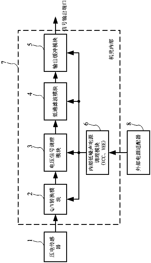
[0048] as attached figure 1 As shown, the structure of the low-noise charge amplifier for piezoelectric sensors of the present invention includes a casing 7, in which there is a charge-to-voltage conversion module 2, a voltage signal conditioning module 3, a low-pass filter module 4, and an output buffer Module 5 and internal low-noise power conditioning module 6, the output terminal of the charge-to-voltage conversion module 2 is connected to the voltage signal conditioning module 3, the output terminal of the voltage signal conditioning module 3 is connected to the low-pass filter module 4, and the output terminal of the low-pass filter module 4 The output is sent to the output port through the output buffer module 5; the internal low-noise power conditioning module 6 is respectively connected to the charge-to-voltage conversion module 2, the voltage signal conditioning module 3, the low-pass filter module 4 and the output buffer module 5 for power supply.

[0049] as attach...

Embodiment 2

[0070] Based on the realization method of the low-noise charge amplifier for the piezoelectric sensor of embodiment 1, the realization method comprises the following steps:

[0071] (1), the charge signal output by the piezoelectric sensor 1 is sent into the charge-to-voltage conversion module 2;

[0072] (2), the charge-to-voltage conversion module 2 converts the charge signal output by the piezoelectric sensor 1 into a weak voltage signal;

[0073] (3), amplify the amplitude of the weak voltage signal to a suitable size through the voltage signal conditioning module 3;

[0074] (4), the adjusted voltage signal is further sent to the low-pass filter module 4 for filtering to reduce high-frequency interference;

[0075] (5) The filtered signal is output from the signal output port via the output buffer module 5 .


PUM


Abstract

The invention discloses a low-noise charge amplifier used for a piezoelectric sensor and a realization method thereof, pertaining to the field of charge-voltage signal conditioning. The technical problem is resolved so that weak charge signals generated by the piezoelectric sensor are collected and amplified. The adopted technical scheme is characterized in that the structure comprises a housing,in which a charge-voltage conversion module, a voltage signal conditioning module, a low-pass filtering module, an output buffer module and an internal low-noise power-conditioning module are arranged; an output end of the charge-voltage conversion module is connected with the voltage signal conditioning module; an output end of the voltage signal conditioning module is connected with the low-passfiltering module; output of the low-pass filtering module is conveyed to an output port through the output buffer module; and the internal low-noise power-conditioning module is connected with the charge-voltage conversion module, the voltage signal conditioning module, the low-pass filtering module and the output buffer module for supply electricity. The invention also discloses the realizationmethod of the low-noise charge amplifier used for the piezoelectric sensor.

Description

technical field [0001] The invention relates to the field of charge-voltage signal conditioning, in particular to a low-noise charge amplifier for piezoelectric sensors and its realization method. Background technique [0002] Piezoelectric crystals can convert input physical quantities such as force, displacement, and acceleration into electric charge output. Piezoelectric crystal sensors designed with this feature have a wide range of applications, such as measuring acceleration, vibration, object deformation, and pressure. [0003] According to the working principle of the piezoelectric sensor, it can be equivalent to a weak charge source with high output impedance. How to collect and amplify the weak charge signal generated by the piezoelectric crystal sensor is a technical problem at present. [0004] Patent No. CN1770627A discloses an automatic feedback control method for an adaptive bias variable gain low noise amplifier. In this method, the charge pump charging netw...

Claims


Application Information

Patent Timeline
Patent Type & Authority Applications(China)
IPC IPC(8): H03F1/26H03F1/30H03F3/70
CPCH03F1/26H03F1/30H03F3/70H03F2200/294
Inventor 董安明李素芳于法鹏舒明雷
Owner QILU UNIV OF TECH