Inertial sensor aliasing interference signal separation method

An inertial sensor and interference signal technology, applied in the directions of instruments, measurement devices, surveying and navigation, etc., can solve problems such as unfavorable engineering implementation of artificial parameter settings, complex interference of inertial sensors, and difficulty in accurate models of interference sources, so as to improve self-adaptation. performance, reduce dependencies, and require less installation conditions

Active Publication Date: 2018-11-13
INST OF OPTICS & ELECTRONICS - CHINESE ACAD OF SCI
View PDF5 Cites 8 Cited by
  • Summary
  • Abstract
  • Description
  • Claims
  • Application Information

AI Technical Summary

Problems solved by technology

Multiple Kalman filtering needs to establish an accurate mathematical model of the interference signal multiple times, and the interference of the inertial sensor is more complicated, it is difficult to obtain an accurate model of each interference source, and the inaccurate

Method used


Image

  • Inertial sensor aliasing interference signal separation method
  • Inertial sensor aliasing interference signal separation method
  • Inertial sensor aliasing interference signal separation method

Examples


Embodiment Construction

[0030] Embodiments of the present invention will be described below in conjunction with the accompanying drawings. However, the following examples are limited to explain the present invention.

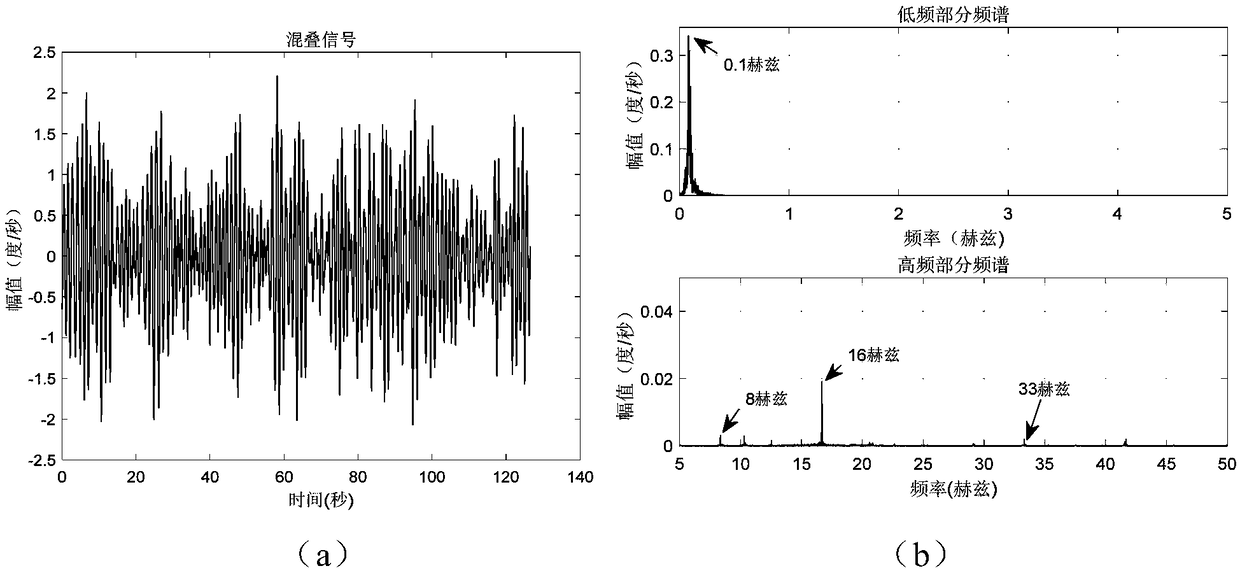
[0031] The following is an example of the aliasing interference signal output by the inertial sensor in the photoelectric tracking system under shipboard conditions. Concrete implementation steps of the present invention are as follows:

[0032] The first step is to analyze the frequency spectrum of the inertial sensor output aliasing signal as figure 1 As shown in the figure, it can be seen from the figure that the aliasing disturbance signal output by the fiber optic gyroscope in the background of the ship is mainly composed of four obvious frequency band signals, which are the low frequency band signal of about 0.1 Hz and the signal of about 10 Hz, about 16 Hz, and 30 Hz. above the high frequency band signal.

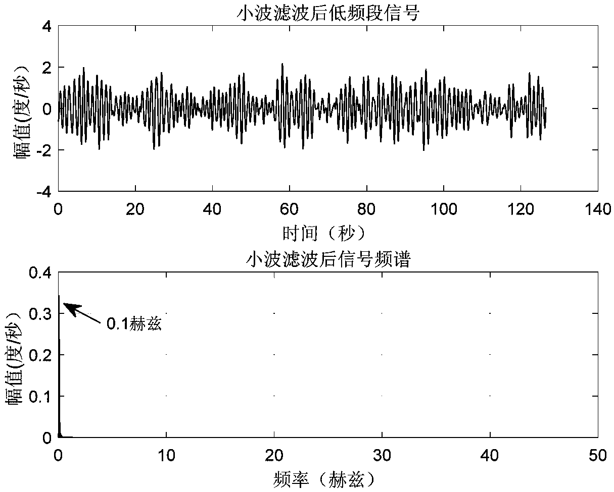
[0033] In the second step, according to the characteristic analysis o...


PUM


Abstract

The invention discloses an inertial sensor aliasing interference signal separation method. The method comprises the following steps that (1) characteristic analysis is conducted on inertial sensor output aliasing signals, and the frequency characteristics of different interference source signals are determined; (2) a threshold function, a wavelet basis and a decomposition level are selected to conduct wavelet filtering on a low frequency section signal in the aliasing signals according to the characteristics of the low frequency section signal; (3) aiming at the high frequency aliasing interference signal subjected to wavelet filtering, N internal empirical mode functions (IMFs) are acquired through self-adapting decomposition of empirical mode decomposition (EEMD); (4) the information content of IMFs is eta, and the number p of the needed IMFs components is calculated and obtained when the eta is larger than or equal to 90 degrees; (5) A PCA algorithm is utilized for dropping N-dimensional IMFs to be P-dimensional; and (6) P-dimensional IMFs is taken as an observation signal, and an appropriate blind source separation algorithm is selected to separate interference source signals at different frequency sections in the high frequency aliasing interference signal. The inertial sensor aliasing interference signal separation method greatly reduces too much man-made experience selections in the signal separation process, and the adaptivity is relatively high.

Description

technical field [0001] The invention belongs to the field of digital signal processing, and in particular relates to a method for separating aliasing signals of inertial sensors, which is used to realize the separation of aliasing interference signals output by inertial sensors in a photoelectric tracking system of a motion platform. Background technique [0002] For the ATP system on a moving carrier, the visual axis will vibrate due to the movement of the carrier and external interference to the carrier, causing the system to deviate from the tracking target, resulting in a decrease in tracking performance. Therefore, the system usually uses an inertial stabilization platform to isolate the interference of the system to the carrier and ensure the stability of the system's boresight. In order to improve the disturbance suppression ability of the inertial stable platform, it is necessary to control all kinds of disturbances received by the system separately. One of the diffi...

Claims


Application Information

Patent Timeline
IPC IPC(8): G01C21/18G01C21/20
CPCG01C21/18G01C21/203
Inventor 胡亭亭包启亮夏运霞唐茂雯
Owner INST OF OPTICS & ELECTRONICS - CHINESE ACAD OF SCI
Why Eureka
Try Eureka