Semi-automatic film expansion machine and film expansion technology
A semi-automatic, film machine technology, applied in semiconductor/solid-state device manufacturing, electrical components, circuits, etc., can solve the problems of limited expansion range, easy to break the film, complex structure, etc., to avoid repeated film expansion, base The effect of high lifting precision and precise control
- Summary
- Abstract
- Description
- Claims
- Application Information
AI Technical Summary
Problems solved by technology
Method used
Image
Examples
Embodiment 1
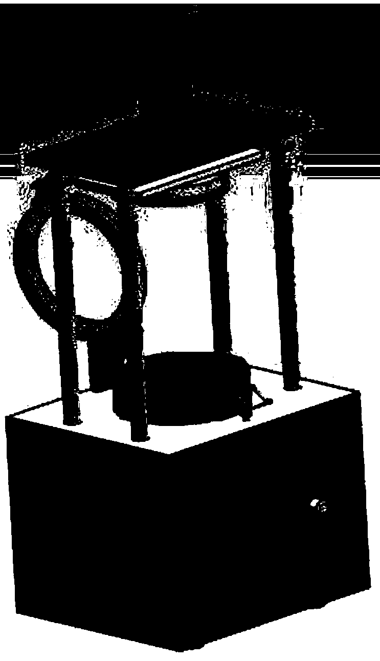
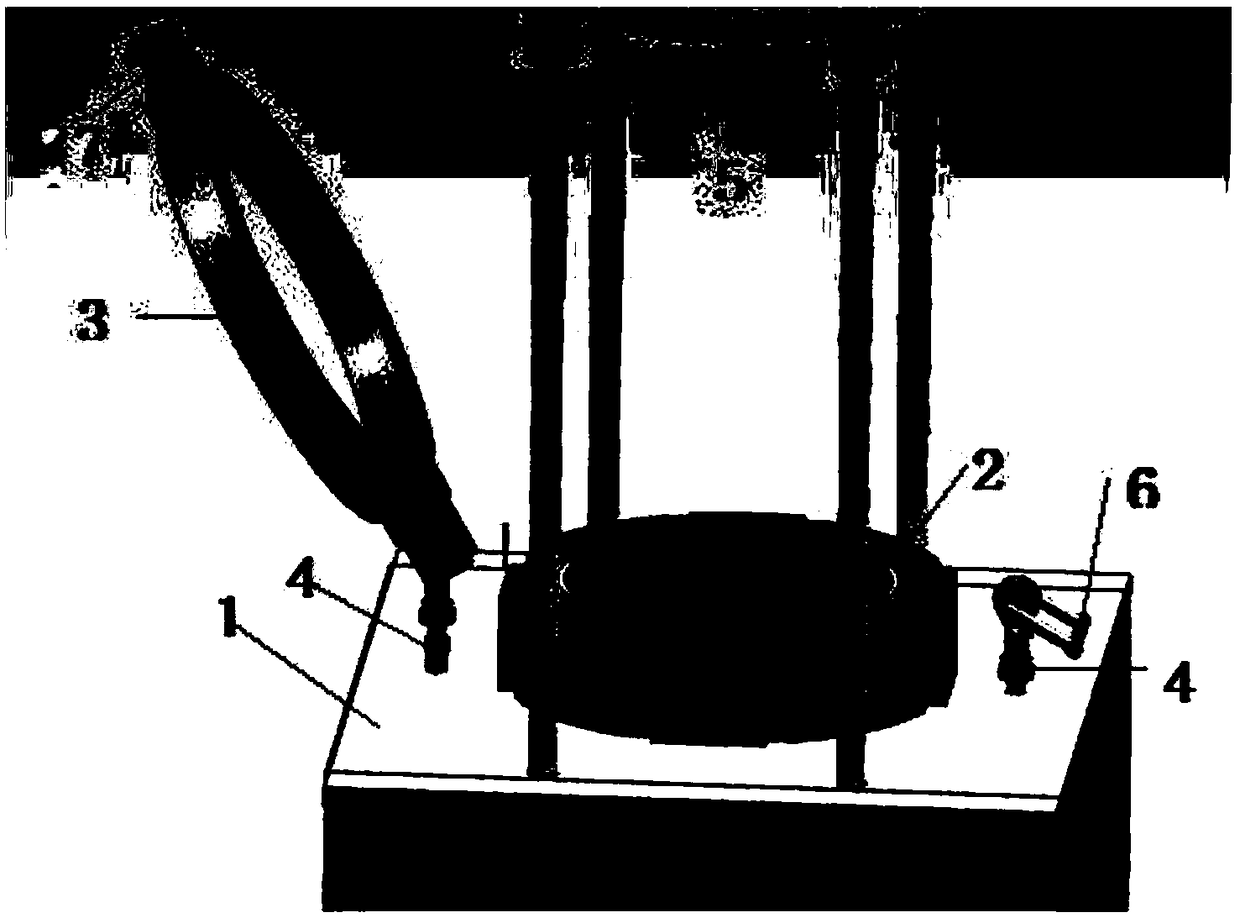
[0019] see Figure 1-2 , a semi-automatic film expanding machine, used for the film expanding process of LED chips packaged at chip size level, is characterized in that: comprising: a working platform 1; a film expanding base 2 that is raised and lowered relative to the working platform 1; 3. The inner diameter of the pressure ring is 200mm, and the outer diameter is 250mm; the working platform 1 is provided with two fixing parts 4, one of the fixing parts 4 is connected with the periphery of the pressure ring 3 through a stainless steel hinge, so that the fixed pressure ring 3 can be in the vertical plane Rotation, the rotation angle of the pressure ring is 0~120°, the other fixing part 4 is provided with a lock 6, and one end of the pressure ring is provided with a protruding buckle 7, which is tightly engaged with the lock 6, and when the pressure ring rotates to the level, the pressure ring 3 The fixing; cover body 5; sub-ring and female ring; heating device; cutting iron ...
Embodiment 2
[0021] A method for film expansion, comprising: step 1) placing a crystal expansion ring on a base; step 2) spreading the expansion blue film with the LED to be tested after scribing on the base of the film expander; step 3) Set the heating temperature of the expanded blue film through the temperature setting button, the heating temperature is 30~60°C; Step 4) Place a 6-inch cutting iron ring on the blue film, and the center of the iron ring coincides with the center of the base of the film expander; Step 5) Put down the pressure ring, lock the lock to make it tightly press the blue film; step 6) According to the distance between the chips, and through the data storage device to record the rising stroke and travel of the base of multiple sets of uniform film expansion Speed, determine the rising height and travel speed of the base, and automatically expand the blue film; Step 7) After the expansion is completed, lower the base to the starting position, unlock the lock, lift the...
Embodiment 3
[0023] When carrying out the film expansion described in embodiment 2, the distance between the chips when the microscope detects the film expansion, the uniformity of the film expansion, when automatically expanding the film, the CCD image acquisition device is compared with the uniform film expansion in the storage device , when the uniformity of the film expansion deviates from a specific value, the control device stops the rise of the base by command, switches to the means of film expansion, and is operated by the workers to manually expand the film.
[0024] The semi-automatic film expansion machine of the present invention can switch between manual film expansion and automatic film expansion, can record the process of uniform film expansion, optimize the key process parameters of rising height and travel speed during film expansion to automatically expand film, and improve production efficiency. The base drive device of the semi-automatic film expander is a series-connec...
PUM
 Abstract
Description
Claims
Application Information
 - R&D
- Intellectual Property
- Life Sciences
- Materials
- Tech Scout
- Unparalleled Data Quality
- Higher Quality Content
- 60% Fewer Hallucinations
Browse by: Latest US Patents, China's latest patents, Technical Efficacy Thesaurus, Application Domain, Technology Topic, Popular Technical Reports.
© 2025 PatSnap. All rights reserved.Legal|Privacy policy|Modern Slavery Act Transparency Statement|Sitemap|About US| Contact US: help@patsnap.com


