MnZn power ferrite material for reducing negative temperature loss and preparation method thereof
A ferrite material and power technology, which is applied in the direction of inorganic material magnetism, inductor/transformer/magnet manufacturing, electrical components, etc. reduce the loss and other issues to achieve the effect of low loss
- Summary
- Abstract
- Description
- Claims
- Application Information
AI Technical Summary
Problems solved by technology
Method used
Image

Examples
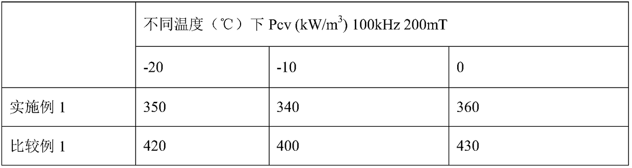
Embodiment 1
[0039] 52.6mol% Fe 2 o 3 And 10.2mol% of ZnO, the rest is the amount of MnO. Mix according to the ratio of ball water to 1:4:0.45, sand and crush in a sand mill for 1 hour, then spray and granulate, and put it into a rotary kiln for pre-calcination at 950°C. 0.04wt% CaCO 3 , 0.025wt% ZrO 2 and 0.35wt% Co 2 o 3 Add it to the calcined material, put the calcined material and additives into a sand mill, grind it for 160 minutes, then spray granulate, and press it into a standard ring under a certain pressure. Put the standard ring into a bell furnace for sintering, and the sintering temperature is 1300°C. Incubate for 5 hours with an oxygen content of 5%. Then cool under the protection of nitrogen. When the temperature drops to 1200°C, the oxygen content is controlled at 0.3%, and at 1150°C, the oxygen content is controlled at 0.95%, so that the MnZn power ferrite material with reduced negative temperature loss is obtained.
Embodiment 2
[0047] 52.7mol% Fe 2 o 3 And 9.7mol% of ZnO, the rest is the amount of MnO. Mix according to the ratio of ball water to 1:4:0.45, sand and crush in a sand mill for 1 hour, then spray and granulate, and put it into a rotary kiln for pre-calcination at 950°C. 0.06wt% CaCO 3 , 0.04wt% ZrO 2 and 0.4wt% Co 2 o 3 Add it to the calcined material, put the calcined material and additives into a sand mill, grind it for 160 minutes, then spray granulate, and press it into a standard ring under a certain pressure. Put the standard ring into a bell furnace for sintering, and the sintering temperature is 1300°C. Incubate for 5 hours with an oxygen content of 6%. Then cool under the protection of nitrogen. When the temperature drops to 1200°C, the oxygen content is controlled at 1.5%, and at 1150°C, the oxygen content is controlled at 0.1%, and then cooled to room temperature under the protection of nitrogen.
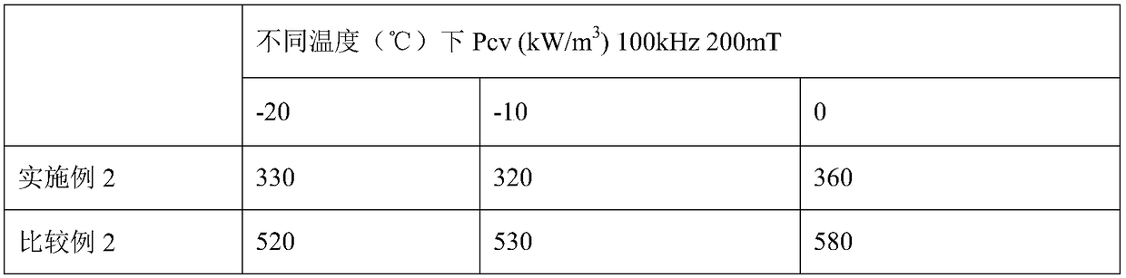
Embodiment 2 and comparative example 2
[0051] Table 2 embodiment 2 and comparative example 2 sample ring test results
[0052]
[0053] As can be seen from Table 2, in Comparative Example 2 Co 2 o 3 The amount is beyond the range of the present invention, resulting in relatively poor loss.
PUM
 Abstract
Description
Claims
Application Information
 - R&D
- Intellectual Property
- Life Sciences
- Materials
- Tech Scout
- Unparalleled Data Quality
- Higher Quality Content
- 60% Fewer Hallucinations
Browse by: Latest US Patents, China's latest patents, Technical Efficacy Thesaurus, Application Domain, Technology Topic, Popular Technical Reports.
© 2025 PatSnap. All rights reserved.Legal|Privacy policy|Modern Slavery Act Transparency Statement|Sitemap|About US| Contact US: help@patsnap.com