Upright magnetorheological polishing device and method

A technology of magnetorheological polishing and magnetorheological fluid, which is applied in the field of polishing, can solve the problems of pollution and corrosive damage, high surface roughness requirements of pipe fittings, high chemical activity, etc., and achieve easy control and adjustment, continuous working efficiency High, with simple effect

Active Publication Date: 2018-11-23
NORTHEASTERN UNIV
View PDF10 Cites 1 Cited by
  • Summary
  • Abstract
  • Description
  • Claims
  • Application Information

AI Technical Summary

Problems solved by technology

Due to the limitation of the use environment, the roughness of the pipe fittings surface is required to be high, mainly to ensure the sealing performance of the pipe fittings at the joints, to prevent the leakage of liquid or gas, which will cause the deterioration of the use environment and cause unnecessary pollution and corrosion. Sexual damage and reduction in service life of pipe fittings
For titanium alloy pipes, especially pipe fittings with small diameters and pipe fittings with surface threads, the traditional polishing method will cause plastic deformation of the pipe fittings or fail to penetrate deep into the thread
Titanium alloy tubes are mainly processed by press hot extrusion and skew rolling perforation. The processed titanium alloy tubes are pickled to remove some surface defects. It is more difficult to comprehensively treat the outer surface of the tube, and the scratches, pits, micro-cracks, and burrs caused by the process will seriously affect the performance in practice
[0004] Titanium alloy is a typical difficult-to-machine material, with high toughness and specific strength, large elastic deformation, and high ch

Method used


Image

  • Upright magnetorheological polishing device and method
  • Upright magnetorheological polishing device and method
  • Upright magnetorheological polishing device and method

Examples


Embodiment Construction

[0034] In order to better explain the present invention and facilitate understanding, the present invention will be described in detail below through specific embodiments in conjunction with the accompanying drawings.

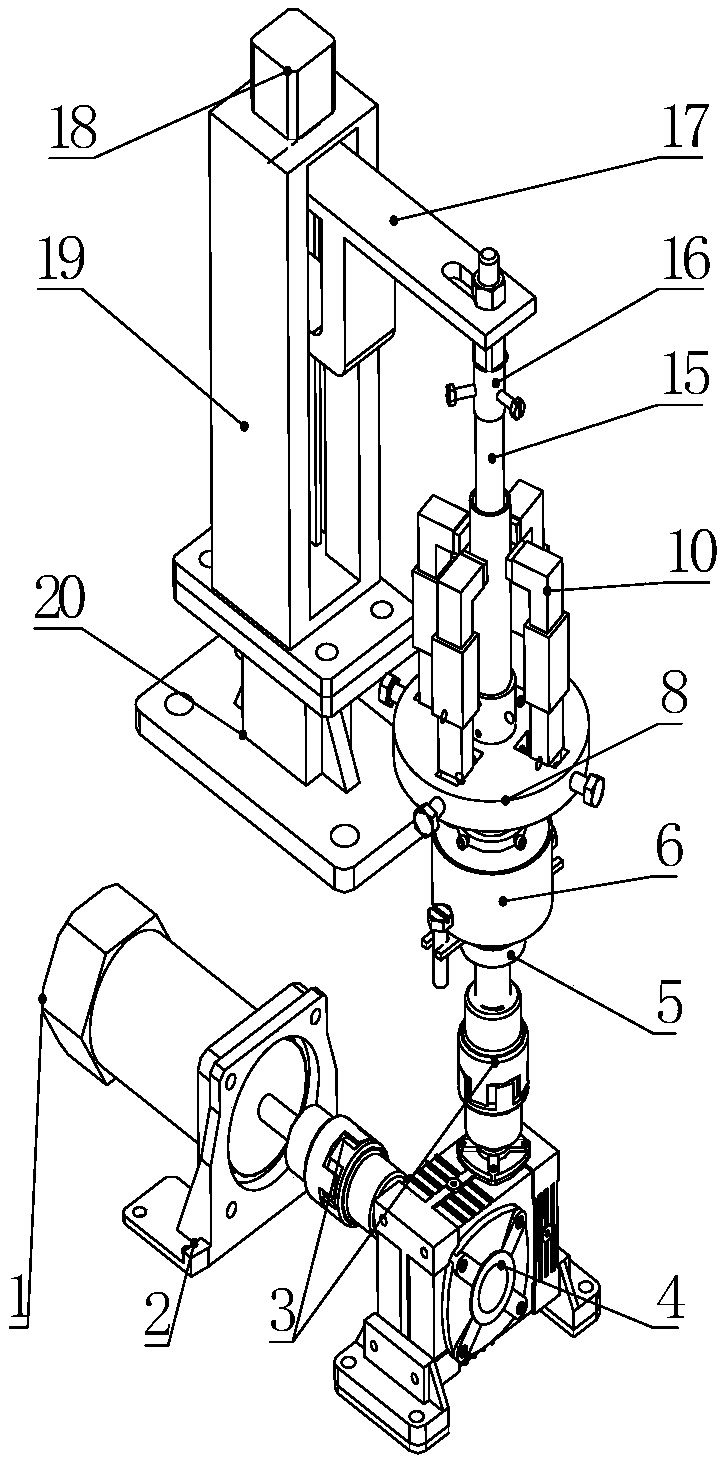
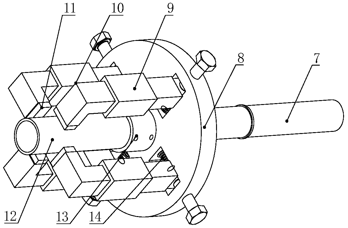
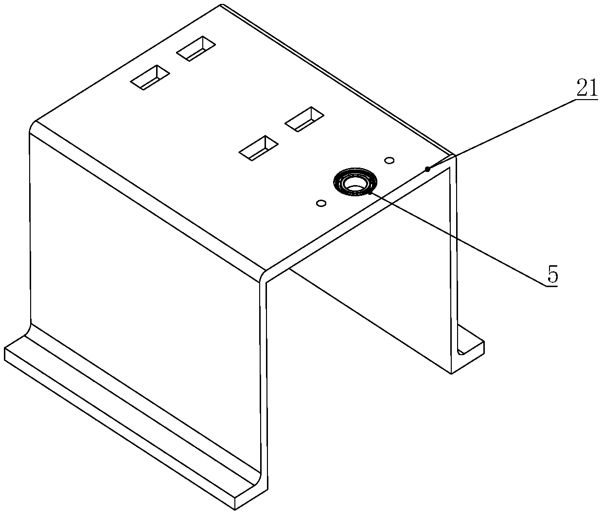
[0035] Such as figure 1 , figure 2 As shown, the magnetic frame 8 is fixedly connected to the rotating shaft 7 of the driving mechanism and rotates with it. The magnetic frame 8 is provided with four iron core supports 10 , and the outer ring of the iron core support 10 is provided with a coil 9 . The rotating shaft 7 passes through the conductive slip ring 6 and is supported by the bearing 5 . The rotor of the conductive slip ring 6 is fixed to the rotating shaft 7 and electrically connected to the coil 9; the stator of the conductive slip ring 6 is relatively fixed and electrically connected to an external power supply. specific reference image 3 , the support member 21 is fixedly arranged relative to the ground, and its upper part is fixed to the outer ...


PUM

PropertyMeasurementUnit
Magnetic field strengthaaaaaaaaaa

Abstract

The invention relates to an upright magnetorheological polishing device. The device comprises a polishing mechanism and a clamping mechanism; the polishing mechanism comprises a magnetic frame, a coiland a vertically arranged liquid storage pipe; the inner hole of the liquid storage pipe fits a workpiece and contains magnetorheological liquid; the workpiece is clamped by the clamping mechanism tofit the position of the liquid storage pipe; a magnetic field is formed in the inner hole of the liquid storage pipe by the coil, and a flexible polishing film is formed by the magnetorheological liquid; the workpiece and the polishing film move relatively in the vertical direction and rotate relatively along the axis of the workpiece. According to the upright magnetorheological polishing deviceand an upright magnetorheological polishing method, a rheologic effect is generated by the magnetorheological liquid to shear the polishing film with higher yield stress and apparent viscosity and viscoplasticity, the relative movement of the magnetorheological liquid and a to-be-processed surface is utilized to perform material removing on the surface, the polishing process is not limited by theshape of the surface of the workpiece, the polishing efficiency is high, and damage is not generated. The device has a simple structure and is easy to control, and workpieces with different characteristics and demands can be polished.

Description

technical field [0001] The invention relates to the field of polishing, in particular to a vertical magnetorheological polishing device. [0002] The invention also relates to a vertical magnetorheological polishing method. Background technique [0003] Titanium alloy tubes have the characteristics of high pressure resistance and corrosion resistance, and are widely used in aerospace, medical, military and other fields. In foreign countries, due to the mature development and supporting application technology of titanium alloy pipes, the development and supporting application technologies of titanium alloy pipes are mature. Therefore, titanium alloy pipes have been used in aviation and aerospace fields in developed countries. Titanium alloy tubes are widely used in bleed air lines, hydraulic lines, and fuel lines of advanced aircraft. Due to the limitation of the use environment, the roughness of the pipe fittings surface is required to be high, mainly to ensure the sealing...

Claims


Application Information

Patent Timeline
IPC IPC(8): B24B1/00
CPCB24B1/005
Inventor 宋万里牛天荧彭珍李红亮
Owner NORTHEASTERN UNIV
Why Eureka
Try Eureka