
Feeder capable of reversely conveying materials, dropping materials from inclined side, reducing interferences and dynamically weighing and metering

A technology of dynamic weighing and reverse blanking, which is applied in the electromechanical field and can solve problems such as belt breakage, large impact force, and large expansion and contraction

Pending Publication Date: 2018-11-23
刘素华
View PDF8 Cites 5 Cited by
  • Summary
  • Abstract
  • Description
  • Claims
  • Application Information

AI Technical Summary

Problems solved by technology

[0002] With the improvement of the conveying function and accuracy of conveying equipment in the society, the requirements for the accuracy and reliability of the dynamic weighing of the reloading and feeding equipment are getting higher and higher. However, in order to save the investment in the silo site and equipment When transferring to the belt conveyor or transport compartment, the distance from the outlet of the silo to the belt conveyor or transport compartment is very close. Since the height of the coal mine silo must be at least 20 meters, the mineral material falling from the coal silo The impact force is very large, which makes the reloading dynamic weighing feeder set at the outlet of the silo to the belt conveyor or the transport compartment vibrate violently, and makes the dynamic weighing feeder set on the reloading dynamic weighing feeder Due to frequent gravity impact and severe shaking of the device, serious weighing errors are caused. In addition, the conveyor belt of the old-style belt weighing feeder and armor belt weighing feeder is fed by the driving roller and driven roller by friction. Belts and armor belts have a large amount of expansion and contraction, which often causes the position of the driving roller and driven roller to be adjusted to match the tension of the belt and armor belt in order to continue working. This led to serious production stoppage accidents caused by the breakage of the first belt of the belt, and often due to excessive tension, the motor power was overloaded when the motor started the belt and the first belt was rotating, resulting in shutdown failures such as motor burnout, and the first belt was attached to the drum. The upper part relies on frictional force to rotate, because when the driving roller and the driven roller are installed, there must be problems that the axes of the two rollers are not parallel and the shaft ends of the two rollers have parallelograms, and because the edge of the belt has no ribs, and there is a gap between the belt piercing strip and the perforation , There are gaps between multiple nail plates, etc., which are affected by tension, temperature, and the deflection of idlers and rollers, etc., which will inevitably lead to the frequent deviation of belts and nail belts during operation, resulting in spilled materials, belts, and nail belts. Faults such as grinding guide trough, belt deviation, tearing and fracture, frequent maintenance and replacement on the site caused serious waste of manpower and material resources, reduced production efficiency and polluted the environment. The old chain belt feeder was worn by multiple strips Multiple nails, material leakage between nails, even if there is a leak-proof strip between the nails, because the leak-proof strips are easy to fall off, material leakage often occurs, and the gap between the nails takes the return journey The material is serious, the manufacturing process of piercing nails is complicated, and the material waste is serious. The chain plate feeder consumes a lot of energy, vibration, and noise during the feeding process. The scraper is higher than the bottom plate and the return material is very serious. And the complex structure, large size and heavy weight, occupying a large site space cause large site infrastructure and equipment investment costs, and a lot of waste of materials. Adding a return material collector at the lower part of the frame not only increases the equipment put into use, but the effect is poor, which further causes a waste of manpower and material resources. The working environment where the dynamic weighing and metering feeder is located has a large temperature difference between day and night, and a larger temperature difference between summer and winter. Large measurement errors are caused. Due to the large weighing error, the transport plane or transport vehicle is often overloaded or seriously short of materials. After the transport vehicle is overloaded, it must find a place to unload the material, and refill the material after the lack of material, which reduces the loading and transportation efficiency. It caused a lot of waste of manpower, space and time, and also caused secondary pollution of materials to the site, air and facilities. In order to solve the above problems, the present invention proposes a dynamic method of reverse feeding inclined side blanking to reduce interference. Weighing dosing feeder

Method used


Image

  • Feeder capable of reversely conveying materials, dropping materials from inclined side, reducing interferences and dynamically weighing and metering
  • Feeder capable of reversely conveying materials, dropping materials from inclined side, reducing interferences and dynamically weighing and metering
  • Feeder capable of reversely conveying materials, dropping materials from inclined side, reducing interferences and dynamically weighing and metering

Examples


Embodiment 1

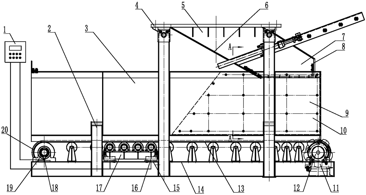
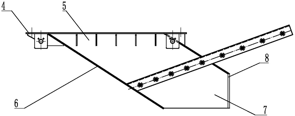
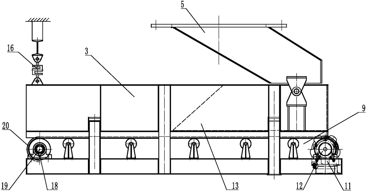
[0089] Figure 1 to Figure 4 It is the reverse feeding oblique side blanking reducing interference dynamic weighing metering feeder described in embodiment 1, including reverse feeding frame 2 and weighing feeder 14, etc., reverse feeding frame 2 Including reverse feeding inclined side blanking material receiver 5 and frame guide groove 3, etc., weighing feeder 14 includes reverse extending feeding device 9, driving device 11 and weighing device 17, etc., reverse feeding inclined The side blanking material receiver 5 includes the articulated inclined plate material guide chute 4, the inclined plate reverse feed guide 6 and the oblique side reverse blanking opening 8, etc., and the reverse extension feeding device 9 includes a driving drum 12, a modified To the roller 19 and the endless conveyor belt 20, etc., the frame guide groove 3 is arranged on the upper part of the endless conveyor belt 20, etc., and the lower part of the inclined plate guide groove part 4 is connected to...

Embodiment 2

[0094] Such as Figure 5 to Figure 8 As shown, it is the reverse feeding slant side blanking reducing interference dynamic weighing metering feeder described in embodiment 2, the frame guide groove 3 and / or the reverse feeding slant side blanking hopper 7, etc. Including the material receiving and conveying shaper 22, the frame guide chute 3 includes the upper feed opening 21 of the feed trough, the left side plate 25 of the feed trough, the right side plate 29 of the feed chute and the rear baffle 27 of the feed trough, etc. The left side plate 25 etc. of the material guide groove are arranged on the left side of the frame material guide groove 3, the material guide groove right side plates 29 etc. are arranged on the right side of the frame material guide groove 3, and the material guide groove back baffle plate 27 etc. are arranged on the guide groove Feed chute rear end and form frame guide hopper 28 etc. with feed chute left side plate 25 and feed chute right side plate 2...

Embodiment 3

[0098] Such as Figure 9 to Figure 14 It is the reverse feeding oblique side blanking reducing interference dynamic weighing metering feeder described in Example 3. The adjustable support 31 includes a screw spacer adjustment support 32 and / or a threaded sleeve guide rod adjustment support 47 etc., the screw spacer adjustment support 32 includes the left screw spacer adjustment support 35 and / or the right screw spacer adjustment support 40, etc., when the left screw spacer adjustment support 35 is used, the left screw spacer adjustment support 35 includes the left adjustment screw 36, the left adjustment spacer 38 and the left adjustment nut 33 etc., the shaper 26 on the left side of the material guide groove also includes the left adjustment shaping plate 39, etc., the left adjustment shaping plate 39 is provided with the left adjustment plate screw hole 37, etc., and in the material guide The left side plate screw hole 34 etc. corresponding to the left adjustment plate screw...


PUM


Abstract

The invention discloses a feeder capable of reversely conveying materials, dropping materials from an inclined side, reducing interferences and dynamically weighing and metering. The feeder comprisesa reverse conveying rack and a weighing conveyor, wherein the reverse conveying rack comprises a reverse-guide inclined-side-dropping receiver and a rack guide slot; the weighing conveyor comprises areverse-extending conveying device, a drive device and a weighing device; the reverse-guide inclined-side-dropping receiver comprises a hanging inclined plate guide slot part, an inclined plate reverse-guide part and an inclined-side reverse dropping hole part; a dropping hole of the inclined-side reverse dropping hole part is formed in a direction reverse to a material moving direction; a weighing sensor supports the reverse-extending conveying device to integrally weigh materials and the reverse-extending conveying device; while inducting weight of flowing materials, the weighing sensor is matched with a speed sensor for weighing the materials, so that effects of reversely conveying materials, dropping materials from the inclined side, reducing interferences and dynamically weighing andmetering are achieved; and hardness and adhesion force of the materials on the weighing conveyor belt are different when the temperature of the conveyor belt changes as tightening force of the conveyor belt is different, so that weighing precision is improved by tens of times.

Description

technical field [0001] The invention relates to the electromechanical field, in particular to a dynamic weighing and metering feeder for reverse feeding and oblique side blanking to reduce interference. Background technique [0002] With the improvement of the conveying function and accuracy of conveying equipment in the society, the requirements for the accuracy and reliability of the dynamic weighing of the reloading and feeding equipment are getting higher and higher. However, in order to save the investment in the silo site and equipment When transferring to the belt conveyor or transport compartment, the distance from the outlet of the silo to the belt conveyor or transport compartment is very close. Since the height of the coal mine silo must be at least 20 meters, the mineral material falling from the coal silo The impact force is very large, which makes the reloading dynamic weighing feeder set at the outlet of the silo to the belt conveyor or the transport compartme...

Claims


Application Information

Patent Timeline
IPC IPC(8): B65G47/18B65G17/06B65G21/20G01G11/00
CPCB65G15/32B65G17/02B65G17/42B65G23/06B65G41/006B65G43/08B65G45/08B65G47/18B65G47/42B65G69/0441B65G2207/20B65G2203/0258B65D88/54B65D90/00B65D90/22B65G17/06B65G21/20B65G41/00B65G43/00B65G47/74B65G65/42B65G69/04F16H9/24G01G11/00
Inventor 刘素华
Owner 刘素华
Learn More