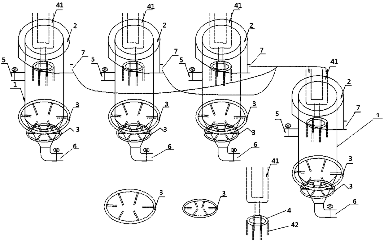
Columnar flotation device for micro-fine particle minerals
A flotation device and column-type technology, applied in the field of fine-grained mineral column-type flotation devices, can solve the problems of consuming pulp energy and wasting energy consumption, and achieve the effects of good mineralization effect, wide adaptability and large specific gravity.
- Summary
- Abstract
- Description
- Claims
- Application Information
AI Technical Summary
Problems solved by technology
Method used
Image
Examples
Embodiment 1
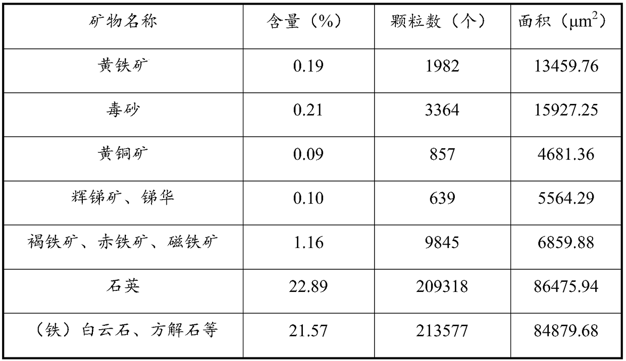
[0041] The ore of a gold mine in Gansu belongs to fine-grained dissemination, containing antimony, arsenic, carbon and other harmful elements. The particle size of the gold inlay is fine, the mineral mud is serious, the oxidation rate is high, the hardness of gold-bearing minerals varies greatly, and the recovery rate of dressing and smelting is low. Process flow and parameters: After the raw ore is crushed, it enters the grinding system with a designed daily processing capacity of 2,000 tons and an actual processing capacity of 2,400 tons. After two stages of closed-circuit grinding, the -200 mesh reaches more than 85%, and the concentration is 21%+-2. The flotation system, after one fine, one coarse, three fine, and four sweeps, the tailings grade is about 1.25g / t, and the tailings are concentrated and classified by 6 sets of 250 cyclones, the bottom flow concentration is 50%, and the fineness is -200 mesh 40 %, the tailings after regrinding and re-selection and the overflow ...
Embodiment 2
[0071] A column type flotation device, comprising a flotation column cylindrical shell (1), a concentrate overflow tank (2) located outside the upper part of the shell, an air duct (3) located at the inner bottom of the flotation column shell, and a The slurry feeder (4) on the upper part of the flotation column, the slurry feeder is connected to the ore inlet pipeline (41), and is located in the middle of the flotation column shell with a tailings discharge outlet (5). The body is also provided with a concentrate discharge port (7), the position of the concentrate discharge port (7) is higher than the tailings discharge port (5), the lower part of the shell is a cone structure, and the cone structure The bottom is equipped with an emergency gate valve port (6), and the tailings discharge port (5) and the emergency gate valve port (6) are all equipped with valve controls;
[0072] The connection between the slurry feeder (4) and the ore inlet pipeline (41) is an annular pipeli...
Embodiment 3
[0082] A column type flotation device, comprising a flotation column cylindrical shell (1), a concentrate overflow tank (2) located outside the upper part of the shell, an air duct (3) located at the inner bottom of the flotation column shell, and a The slurry feeder (4) on the upper part of the flotation column, the slurry feeder is connected to the ore inlet pipeline (41), and is located in the middle of the flotation column shell with a tailings discharge outlet (5). The body is also provided with a concentrate discharge port (7), the position of the concentrate discharge port (7) is higher than the tailings discharge port (5), the lower part of the shell is a cone structure, and the cone structure The bottom is equipped with an emergency gate valve port (6), and the tailings discharge port (5) and the emergency gate valve port (6) are all equipped with valve controls;
[0083] The connection between the slurry feeder (4) and the ore inlet pipeline (41) is an annular pipeli...
PUM
 Abstract
Description
Claims
Application Information
 - R&D
- Intellectual Property
- Life Sciences
- Materials
- Tech Scout
- Unparalleled Data Quality
- Higher Quality Content
- 60% Fewer Hallucinations
Browse by: Latest US Patents, China's latest patents, Technical Efficacy Thesaurus, Application Domain, Technology Topic, Popular Technical Reports.
© 2025 PatSnap. All rights reserved.Legal|Privacy policy|Modern Slavery Act Transparency Statement|Sitemap|About US| Contact US: help@patsnap.com


