Pressure gas balance system structure of turbocharger

A turbocharger, pressurized gas technology, used in machinery/engines, liquid fuel engines, components of pumping devices for elastic fluids, etc. Increase the pressure ratio, affect the reliability of the supercharger and the internal combustion engine, etc., to achieve the effect of convenient implementation

Active Publication Date: 2018-12-07
大连中车泽通电气有限公司 +1
View PDF7 Cites 0 Cited by
  • Summary
  • Abstract
  • Description
  • Claims
  • Application Information

AI Technical Summary

Problems solved by technology

[0002] As the load of the internal combustion engine increases, the operating speed and pressure ratio of the turbocharger increase accordingly. Under the background of high-speed and large-diameter application of the traditional aluminum alloy compressor impeller of the turbocharger, its working time is different from that of the inhaled The temperature of the surface material of the impeller caused by the friction of compressed air also increases accordingly. The long-term use of the compressor impeller at this high temperature and high speed will obviously reduce the mechanical properties and fatigue life of its aluminum alloy material, and affect the performance of the supercharger and internal combustion engine. Use reliability
[0003] The turbocharger scroll end seal structure will reduce the oil sealing ability due to carbon deposits during long-term use. When the turbocharger is used at low speed, the sealing ability of the reverse thread labyrinth structure will also be weak due to the low speed, making the bearing The lubricating oil in the oil return chamber of the casing overflows through the gap of the sealing structure, causing serious oil leakage or carbon deposits in the supercharger

Method used


Image

  • Pressure gas balance system structure of turbocharger

Examples


Embodiment Construction

[0016] In order to make the purpose, technical solutions and advantages of the embodiments of the present invention clearer, the technical solutions in the embodiments of the present invention will be clearly and completely described below in conjunction with the drawings in the embodiments of the present invention. Obviously, the described embodiments It is a part of embodiments of the present invention, but not all embodiments. Based on the embodiments of the present invention, all other embodiments obtained by persons of ordinary skill in the art without creative efforts fall within the protection scope of the present invention.

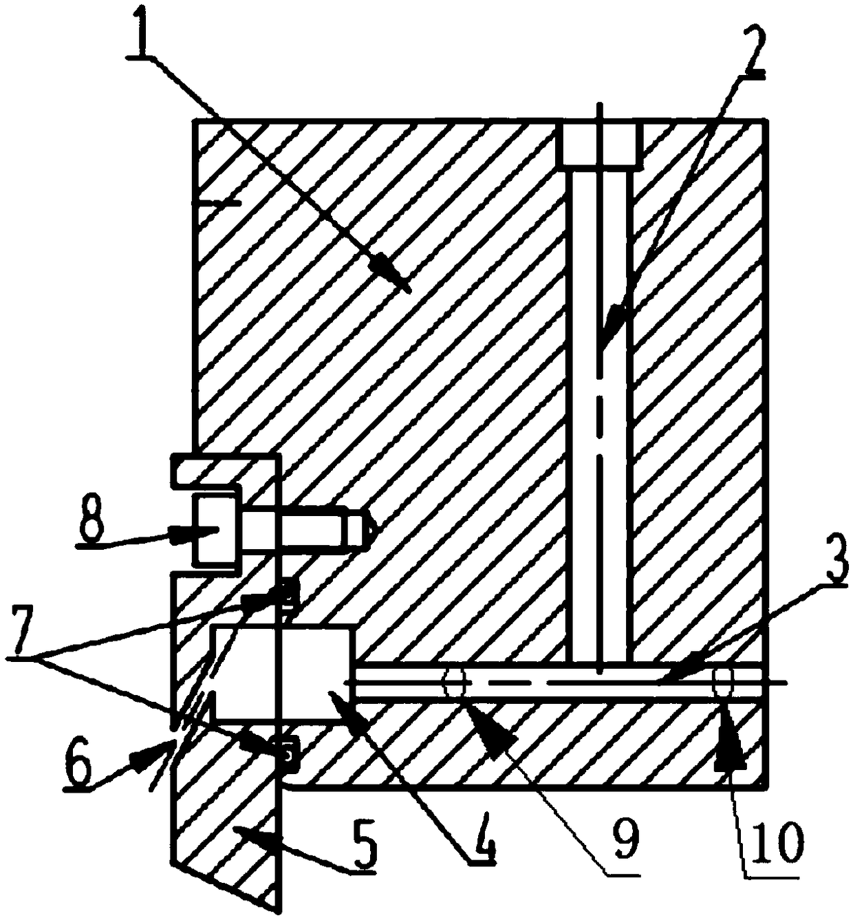
[0017] figure 1 It is a structural schematic diagram of the turbocharger pressure gas balance system of the present invention, as figure 1 As shown, the structure of this embodiment may include:

[0018] The pressure gas inlet passage opened in the intermediate body, the balance passage communicated with the pressure gas inlet passage, one end o...


PUM


Abstract

The invention discloses a pressure gas balance system structure of a turbocharger. The structure comprises a pressure gas entering channel formed in a middle body, and a balance channel communicatingwith the pressure gas entering channel, one end of the balance channel is connected with an annular cavity of a gas compressor gas seal cavity on the gas compressor end, and the other end of the balance channel communicates with the a turbine end oil and gas seal structure. The system structure schemes of gas compressor impeller blade back cooling function and the turbine end oil and gas seal function can be simultaneously or independently achieved, and on the premise of not increasing other parts, not damaging the pressurizer whole structure, not affecting the whole property and reliability of a pressurizer, the problem that the gas compressor impeller blade back cooling function and the turbine end oil and gas seal function are not associated, and even conflict and intervene can be solved.

Description

technical field [0001] The invention relates to the technical field of turbochargers, in particular to a structure of a turbocharger pressure gas balance system. Background technique [0002] As the load of the internal combustion engine increases, the operating speed and pressure ratio of the turbocharger increase accordingly. Under the background of high-speed and large-diameter application of the traditional aluminum alloy compressor impeller of the turbocharger, its working time is different from that of the inhaled The temperature of the surface material of the impeller caused by the friction of compressed air also increases accordingly. The long-term use of the compressor impeller at this high temperature and high speed will obviously reduce the mechanical properties and fatigue life of its aluminum alloy material, and affect the performance of the supercharger and internal combustion engine. Use reliability. [0003] The turbocharger scroll end seal structure will re...

Claims


Application Information

Patent Timeline
Patent Type & Authority Applications(China)
IPC IPC(8): F02B39/00F01D11/04F01D11/06F04D29/58
CPCF01D11/04F01D11/06F02B39/00F04D29/5846
Inventor 张博睿高博闻俊夫
Owner 大连中车泽通电气有限公司
Why Eureka
Try Eureka