Eureka AIR delivers breakthrough ideas for toughest innovation challenges, trusted by R&D personnel around the world.

A proton exchange membrane fuel cell unit, a fuel cell stack, an assembly process and a control method

A fuel cell unit and proton exchange membrane technology, which is applied to fuel cells, fuel cell parts, electrical components, etc., can solve the problems of high technical requirements for assembly processes, unsuitable for large-scale production, and high engineering difficulties. The effect of solving electrochemical corrosion, overcoming corrosion problems, and simplifying assembly difficulty

Active Publication Date: 2018-12-07
上海轩玳科技有限公司
View PDF5 Cites 11 Cited by
  • Summary
  • Abstract
  • Description
  • Claims
  • Application Information

AI Technical Summary

Problems solved by technology

The conduction of the current is completed by mechanical contact. The power characteristics of this fuel cell structure mainly depend on the size of the contact resistance provided by the mechanical fastening force, and it changes with the alternation of the mechanical fastening force. It requires a lot of assembly technology. High, not suitable for large-scale production. At the same time, the supply of hydrogen and oxygen is provided through openings, sealing, and serial supply on the bipolar plate of each fuel cell unit. The gas seal of the entire system depends on the mechanical preload and the compression of the sealing ring. Quantity is guaranteed, the project is difficult, and mass production is difficult

Method used


Image

  • A proton exchange membrane fuel cell unit, a fuel cell stack, an assembly process and a control method
  • A proton exchange membrane fuel cell unit, a fuel cell stack, an assembly process and a control method
  • A proton exchange membrane fuel cell unit, a fuel cell stack, an assembly process and a control method

Examples


Embodiment Construction

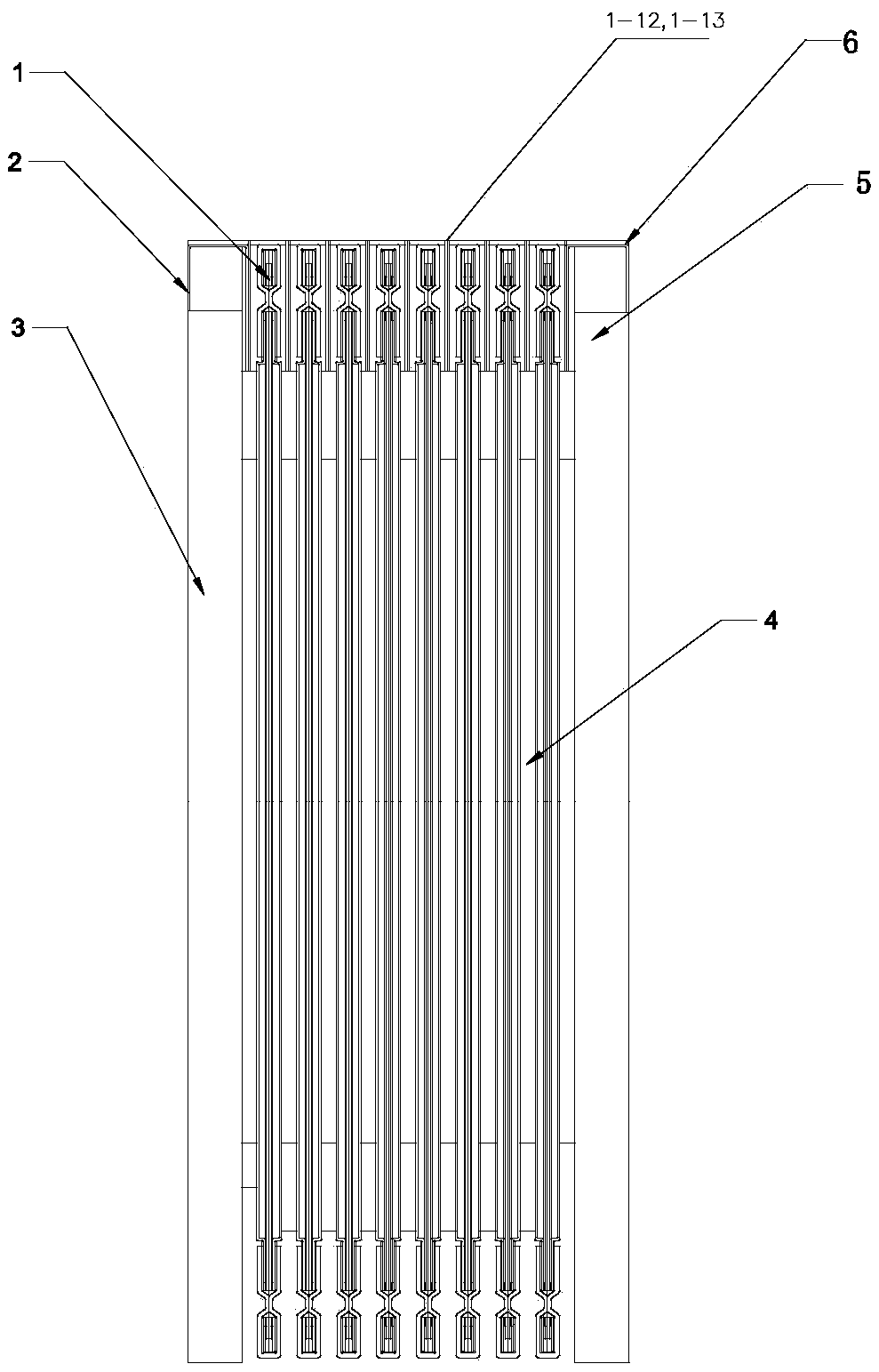
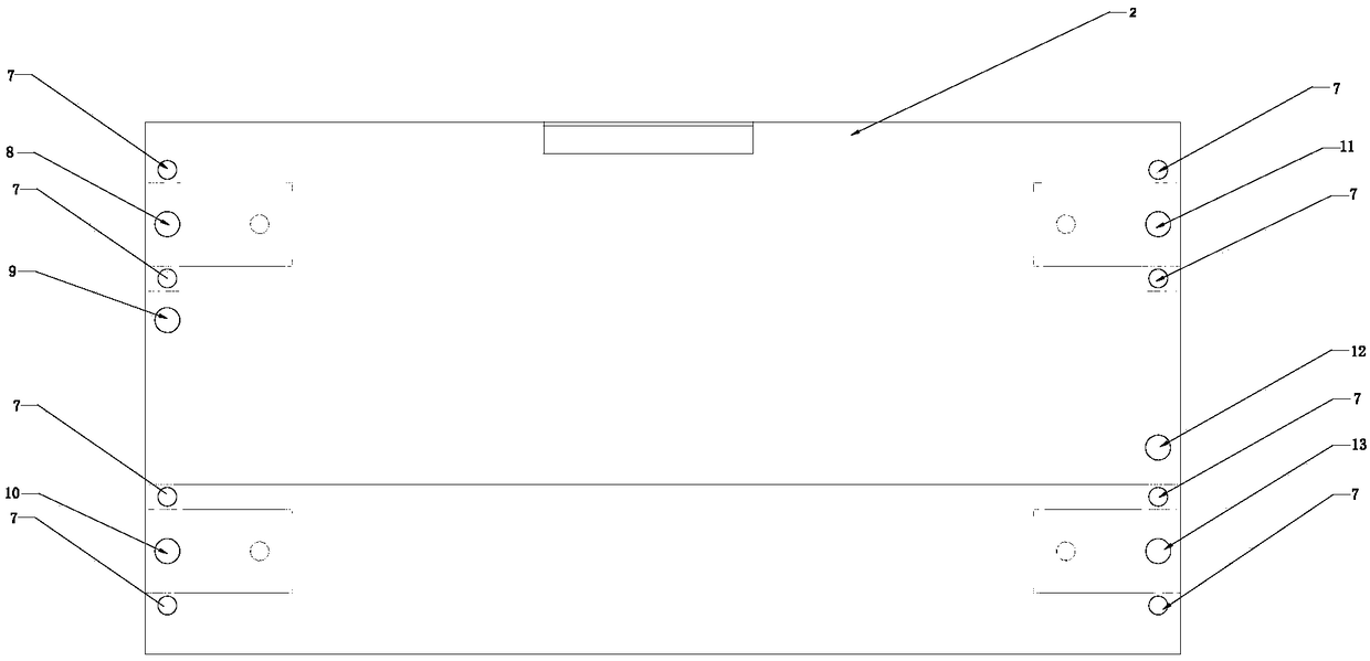
[0031] figure 1 It is a schematic cross-sectional view of a fuel cell stack of the present invention. figure 2 It is a schematic front view of a fuel cell stack of the present invention. image 3 It is a schematic side view of the composition structure of a fuel cell unit of the present invention. Figure 4 It is a schematic front view of the composition structure of a fuel cell unit of the present invention. Figure 5 It is a structural explosion diagram of a fuel cell unit of the present invention. In the drawings, the reference signs are as follows: 1 is the fuel cell unit, 2 is the positive terminal, 3 is the first end plate, 4 is the liquid cooling plate, 5 is the second end plate, 6 is the negative terminal, 7 is Battery stack fastening bolts, 8 is the hydrogen inlet, 9 is the coolant outlet, 10 is the hydrogen outlet, 11 is the oxygen inlet, 12 is the coolant inlet, and 13 is the oxygen outlet. 1-1, 1-2 are hydrogen distributors, 1-3 are negative (hydrogen) flow fi...


PUM


Abstract

The invention relates to a proton exchange membrane fuel cell unit and a cell stack, belonging to the technical field of hydrogen fuel cells. The battery unit is composed of hydrogen distributor, negative electrode flow field plate, membrane module MEA, positive electrode flow field plate and oxygen distributor. The hydrogen inlet and outlet are connected with the hydrogen inlet and outlet of negative electrode flow field plate respectively. The oxygen inlet and outlet are connected with the oxygen inlet and outlet of positive electrode flow field plate respectively. As that battery unit of the invention has independent hydrogen and oxygen supply port, the bipolar plate in the prior art is canceled, and the heat dissipation is replace by the liquid cooling circulation in the original structure through the external heat dissipation device, thereby avoiding the risk of the coolant leaking inside the battery, and at the same time, the gas quantity of each battery unit can be timely controlled, so as to ensure that the battery is not invalidated due to the anti-polar reaction. The series welding structure of the positive and negative electrodes of the battery cell is adopted to reducethe series resistance and improve the power characteristics. Greatly reducing manufacturing costs; Simplified manufacturing and assembly process facilitates large-scale production.

Description

technical field [0001] The invention relates to a proton exchange membrane fuel cell structure, in particular to a proton exchange membrane fuel cell unit, a fuel cell stack, an assembly process and a control method, and belongs to the technical field of hydrogen fuel cells. Background technique [0002] Lithium-ion power batteries have been popularized and applied in pure electric vehicles as an energy storage device. However, due to their long charging time and short driving range, pure electric vehicles are only suitable for personal short-distance transportation. The tool's most likely solution focuses on hydrogen proton exchange membrane fuel cell systems. [0003] With the development of new energy technology and material technology, the bottleneck technology of hydrogen production, storage and transportation has been solved; the progress of catalyst preparation technology has greatly reduced the application load of noble metal catalysts. At the same time, the applicat...

Claims


Application Information

Patent Timeline
Patent Type & Authority Applications(China)
IPC IPC(8): H01M8/02H01M8/04029H01M8/2465
CPCH01M8/02H01M8/04029H01M8/2465Y02E60/50Y02P70/50
Inventor 娄豫皖和祥运
Owner 上海轩玳科技有限公司
Why Eureka
Eureka Blog
Learn More