Bottoming welding method of laser-hot wire MIG composite based on light beam scanning

A welding method and beam scanning technology, which is applied in the field of laser-hot wire MIG composite backing welding, can solve the problem that the back of the liquid metal weld is easy to form concaves, etc.

Inactive Publication Date: 2018-12-11
HARBIN IRT INTELLIGENT ROBOT TECH CO LTD
View PDF7 Cites 9 Cited by
  • Summary
  • Abstract
  • Description
  • Claims
  • Application Information

AI Technical Summary

Problems solved by technology

[0012] The purpose of the present invention is to solve the problem that the back of the liquid metal weld is easy to form concave during the ex

Method used


Image

  • Bottoming welding method of laser-hot wire MIG composite based on light beam scanning
  • Bottoming welding method of laser-hot wire MIG composite based on light beam scanning

Examples


specific Embodiment approach 1

[0019] Specific implementation mode one: combine figure 1 and figure 2 Describe this embodiment mode, a laser-hot wire MIG composite bottoming welding method based on beam scanning described in this embodiment, the bottoming welding method includes: a laser beam scanned along a certain trajectory and a hot wire protected by an inert gas MIG arc combination is used for backing welding. The laser beam and arc act in a welding pool. By reasonably matching the power of the laser beam, scanning frequency, and laser swing, it can stir the welding pool to a certain extent and change the welding pool. The stressed state of the pool, thus completing the root welding of the workpiece to be welded.

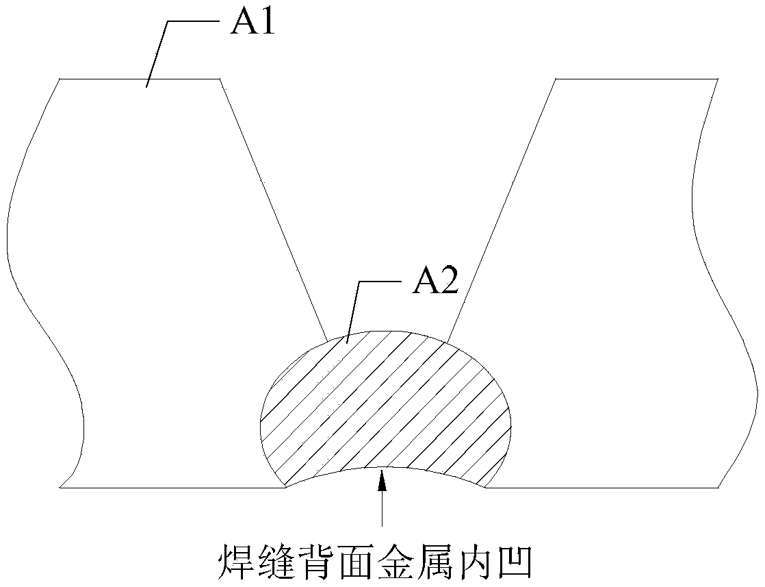
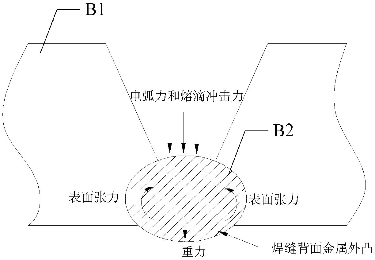
[0020] In this embodiment, the laser beam scanning technology is used to stir the welding pool of the workpiece to be welded, changing the hand state of the welding pool and reducing the resistance of the liquid metal to the root of the groove , improve the forming effect of the back of t...

specific Embodiment approach 2

[0021] Specific embodiment 2: This embodiment is a laser-hot wire MIG composite bottoming welding method based on beam scanning described in specific embodiment 1. In this embodiment, the laser beam and the MIG arc are compounded. For: paraxial compound mode;

[0022] The paraxial composite method is specifically: the laser beam is in front, the MIG arc is behind, the inclination angle of the laser beam is controlled between 80° and 90°, the inclination angle of the MIG arc welding torch is controlled between 55° and 65°, and the light The wire pitch is 0mm to 8mm.

specific Embodiment approach 3

[0023] Specific embodiment three: This embodiment is a laser-hot wire MIG composite welding method based on beam scanning described in specific embodiment one. In this embodiment, the shape of the scanning trajectory of the laser beam is circular, One of elliptical, S-shaped or zigzag, the scanning frequency F of the laser beam is greater than or equal to 100HZ, and the scanning width B of the laser beam is in the range of 2mm-5mm.


PUM

PropertyMeasurementUnit
Defocus amountaaaaaaaaaa

Abstract

The invention provides a bottoming welding method of laser-hot wire MIG composite based on light beam scanning, relates to the field of laser-hot wire MIG composite welding, and solves the problem that liquid metal welding joint back surface is prone to forming an indent when an existing laser-hot wire MIG welding performs bottoming welding. Bottoming welding is carried out on laser beam and hot wire MIG electric arc composite, wherein the laser beam scans along a certain track, and the hot wire MIG electric arc composite is protected by insert gas. The laser beam and the electric arc act in awelding pool, the power, scanning frequency and laser swing of the laser beam are matched reasonably to achieve a certain stirring action for the welding pool, the stress state of the welding pool ischanged, and the bottoming welding of welded workpieces is completed. The bottoming welding method of the laser-hot wire MIG composite based on the light beam scanning has the beneficial effects thatthe stirring action is achieved for the laser scanning, the stress state of the welding pool is changed, the resistance of the liquid metal flowing to a groove root portion is reduced, the forming effect of the welding joint back surface is improved, and the forming of the welding joint back surface is quite attractive and the spread-ability of the welding joint is good.

Description

technical field [0001] The invention relates to a laser-hot wire MIG composite backing welding technology. Background technique [0002] Because TIG welding is protected by pure Ar, the welding process is stable, the weld shape is beautiful, the weld metal is clean, and the metallurgical performance of the welded joint is high. For TIG root welding, in order to ensure the penetration and back forming of the weld root, the following two methods are mainly used: [0003] (1) Larger groove angle (60°-70°), resulting in low welding efficiency, large consumption of welding materials, large welding heat input, and easily lead to large welding deformation; [0004] (2) A certain gap needs to be left at the root of the groove. The uneven size of the gap will directly affect the penetration of the root of the weld and the formation of the back. ; [0005] Therefore, with the rapid development of my country's aviation, aerospace, nuclear power and other fields, TIG welding methods ...

Claims


Application Information

Patent Timeline
IPC IPC(8): B23K26/348
CPCB23K26/348
Inventor 王小朋李海超时威刘宇金盛文松
Owner HARBIN IRT INTELLIGENT ROBOT TECH CO LTD
Why Eureka
Try Eureka