Novel air-breathing pulse detonation engine system on basis of two-stage detonation

An engine system and pulse detonation technology, which is applied in the direction of engine components, charging system, turbine/propulsion device air intake, etc., can solve the problem of difficult performance guarantee, long-term stable operation of the engine, and failure to effectively prevent detonation. High-temperature and high-pressure air flow reverse transmission and other problems, to achieve the effect of increasing the single intake air volume, simple system structure, and strong flow resistance

Inactive Publication Date: 2018-12-11
NORTHWESTERN POLYTECHNICAL UNIV
View PDF0 Cites 2 Cited by
  • Summary
  • Abstract
  • Description
  • Claims
  • Application Information

AI Technical Summary

Problems solved by technology

[0003] Since the generation of detonation waves is intermittent and periodic, a higher operating frequency is one of the necessary conditions for increasing the thrust of the detonation engine and improving the working stability of the detonation engine; however, limited by the current conventional valve technology, it is very difficult to It is difficult to ensure the high frequency, large flow and high reliability requirements of the valve system switch at the same time
Existing high-frequency solenoid valves are difficult to ensure the large flow path requirements required by industrial engines at high frequencies, and it is also difficult to ensure the long-term stable operation requirements of engines; it is difficult for conventional valves to ensure the high-frequency flow required by detonation engines. switch requirements
[0004] Although the existing air-breathing detonation engine system can self-inhale air as an oxidant to realize high-frequency and high-flow operation, it cannot effectively prevent the high-temperature and high-pressure airflow generated by detonation from back-propagating, and its working performance is difficult to guarantee

Method used


Image

  • Novel air-breathing pulse detonation engine system on basis of two-stage detonation
  • Novel air-breathing pulse detonation engine system on basis of two-stage detonation
  • Novel air-breathing pulse detonation engine system on basis of two-stage detonation

Examples


Embodiment Construction

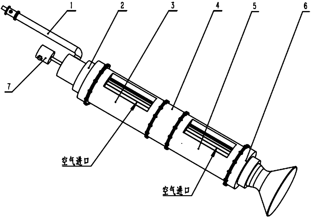
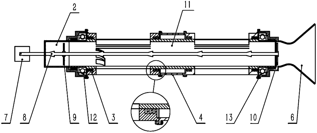
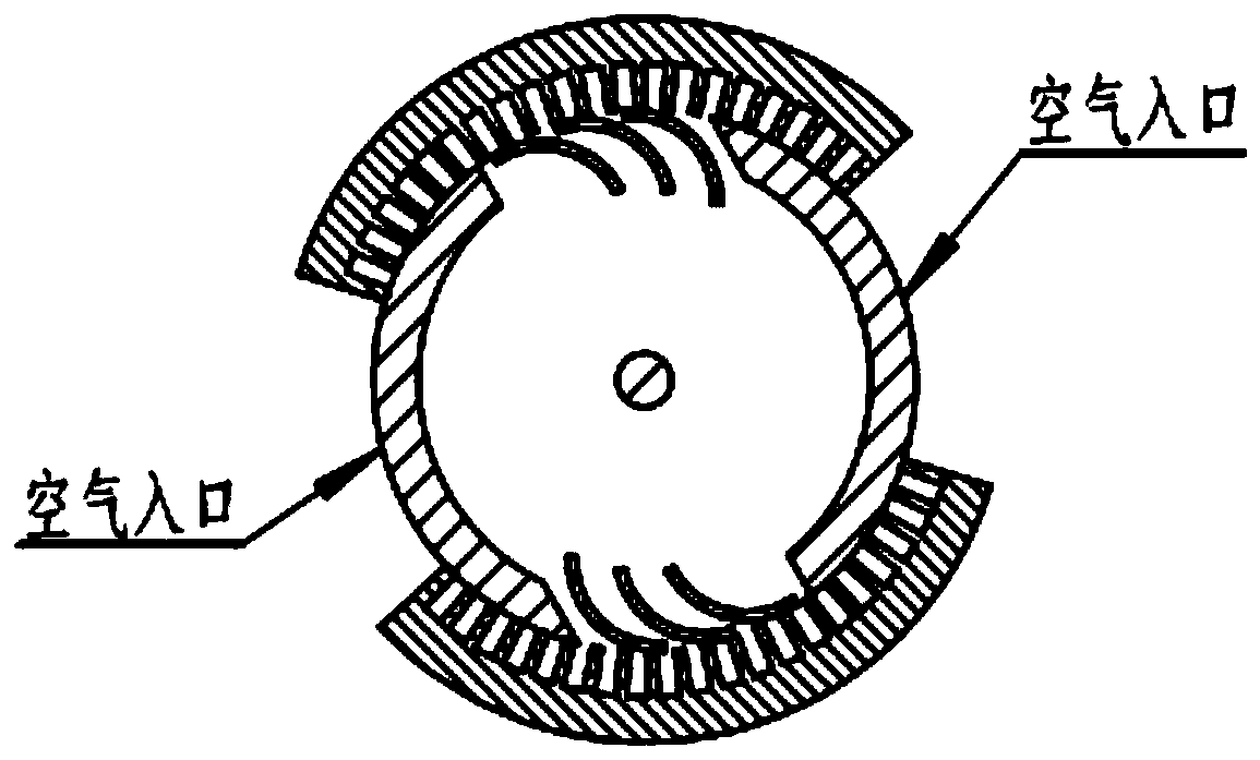
[0027] see figure 1 — Figure 9 , a new air-breathing pulse detonation engine system, including air supply system, detonation system, detonation chamber system, fuel supply system, each component such as figure 1 with figure 2 Assembled as shown, the rest of the system is as Figure 8 Connect as shown. The number and arrangement of the detonation chamber system are determined according to the power required by the aircraft and the structure of the aircraft. The air required for each detonation chamber is provided by an air intake distributor; the air intake distributor connects two air intake systems and sealed pipes- The air inlets of 3 and 5; the main detonation chamber-11 is supported by bearings-12 and 13 installed at both ends of the main detonation chamber, the head of the main detonation chamber-2 is connected with the stationary outer ring of the bearing-12, and detonation Pipe-1 is installed on the head of the main detonation chamber-2, tail nozzle-6 is connected...


PUM


Abstract

The invention discloses a novel air-breathing pulse detonation engine which comprises air supply systems, detonation chamber systems, initiation systems, fuel oil supply systems and corresponding control systems. The novel air-breathing pulse detonation engine is mainly characterized in that main detonation chambers are unique high-speed rotary components and can rotate, accordingly, air intermittent filling can be controlled, and internal intermittent detonation combustion can be carried out on the main detonation chambers. The novel air-breathing pulse detonation engine has the advantages that a method for effectively increasing the operating frequencies of the novel air-breathing pulse detonation engine on the premise that the filling volumes of detonable mixtures are not decreased is provided, accordingly, the problem of fuel gas reverse transmission of existing air-breathing pulse detonation engines can be solved to a certain extent, and a novel way can be provided to developing practical high-power detonation engines.

Description

technical field [0001] The invention relates to the technical field of aerospace engines, in particular to a novel air-breathing pulse detonation engine system based on two-stage detonation. Background technique [0002] The invention of aerospace vehicles has opened a new chapter in the development of human beings in the field of aerospace. The successive advent of various aviation and aerospace engines has accelerated the pace of mankind's march into aerospace. At the same time, the complex flight environment puts forward strict requirements for the propulsion system such as high performance, wide speed range, and wide airspace. The existing aerospace power plant is mainly based on the conventional isobaric combustion method, and its technical level has developed to a fairly mature stage, so it is difficult to further improve its performance. As a new type of power plant based on the detonation thermodynamic cycle, the detonation engine has potential performance advantage...

Claims


Application Information

Patent Timeline
Patent Type & Authority Applications(China)
IPC IPC(8): F02K7/02F02C7/04
CPCF02K7/02F02C7/04
Inventor 范玮谭风光鲁唯
Owner NORTHWESTERN POLYTECHNICAL UNIV
Why Eureka
Try Eureka