A biomass flow fuel cell system
A fuel cell system and biomass liquid technology, which is applied in the direction of regeneration of fuel cells, fuel cells, circuits, etc., can solve the problems of low power generation efficiency, easy deactivation of catalysts, and low cycle utilization rate.
- Summary
- Abstract
- Description
- Claims
- Application Information
AI Technical Summary
Problems solved by technology
Method used
Image
Examples
Embodiment 1
[0034] 1. Oxidative degradation of rice straw for 2.5 hours: Dissolve 25g of ferric chloride hexahydrate and 6mL of concentrated hydrochloric acid in 44mL of deionized water, then add 2g of rice straw, heat to 113°C for 2.5h, filter the reaction solution, and dry the filter residue at low temperature ,stand-by.
[0035] 2. Oxidative degradation of rice straw for 5 hours: Dissolve 25g of ferric chloride hexahydrate and 6mL of concentrated hydrochloric acid in 44mL of deionized water, then add 2g of rice straw, heat to 113°C for 5h, filter the reaction solution, dry the filter residue at low temperature, and wait for use.
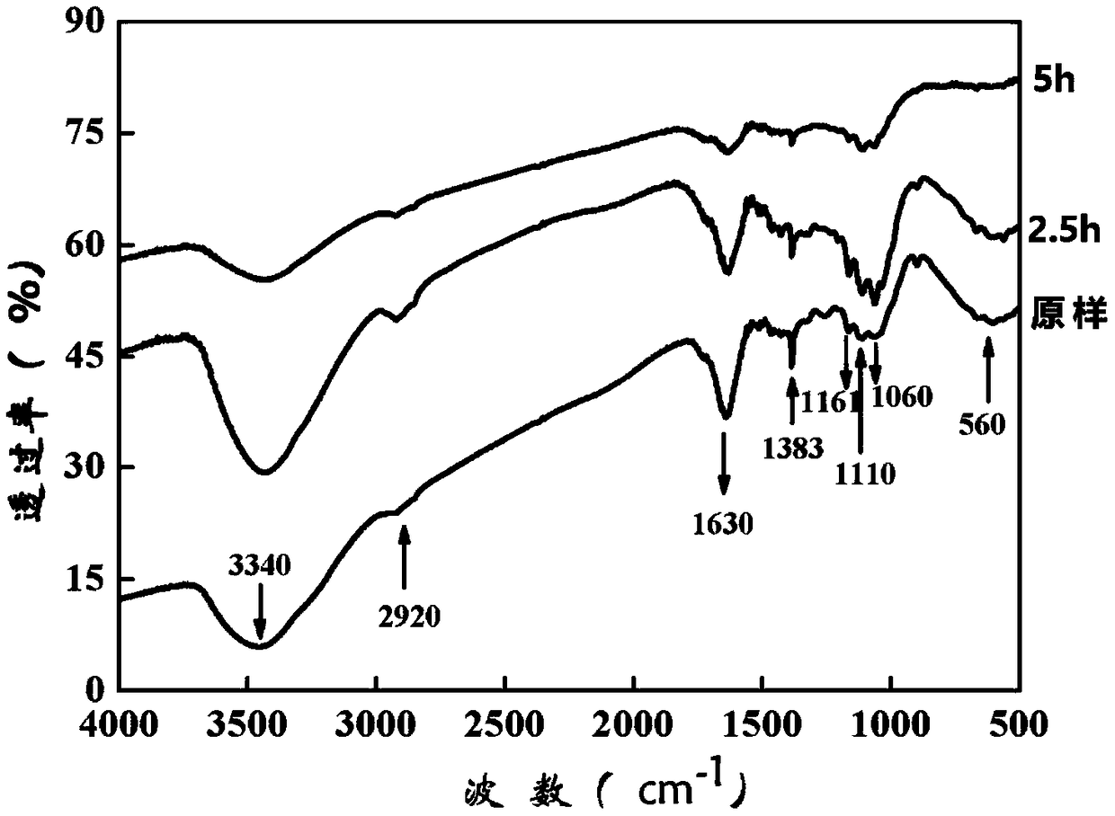
[0036] 3. Conduct infrared test on the solid product filter residue of the rice straw as it is, at 2.5h and 5h, and the results are as follows: figure 1 shown. The infrared spectrogram analysis is as follows: Compared with the untreated rice straw, the peak shapes of the 2.5h and 5h spectrograms are obviously different. 2920cm in original condition -1 The...
Embodiment 2
[0038] 1. Prepare ferrous anolyte: Dissolve 25g of ferric chloride hexahydrate and 6mL of concentrated hydrochloric acid in 44mL of deionized water, then add 2g of rice straw, heat to 113°C for 5 hours, and set aside.
[0039] 2. Preparation of pentavalent vanadium catholyte: Add 20g of vanadium pentoxide into 524mL of deionized water, stir under ice bath, then add 76mL of concentrated sulfuric acid, continue to stir for 5h, and set aside.
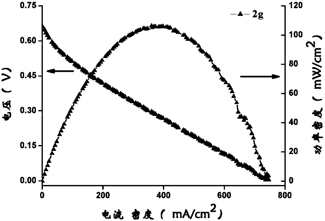
[0040] 3. Put the prepared ferrous iron anolyte and pentavalent vanadium catholyte into the anolyte tank and catholyte tank at 80°C respectively, and use a peristaltic pump to transport the anolyte and catholyte to the anode and cathode of the battery respectively, Then use the electrochemical workstation to test the battery to detect the output voltage, current density, and power density of the battery. The results are as follows: figure 2 As shown, the maximum output voltage of the battery prepared in Example 2 is 0.66mV, and the maximu...
Embodiment 3
[0042] 1. Prepare ferrous anolyte: Dissolve 30g of ferric chloride hexahydrate and 12mL of concentrated hydrochloric acid in 48mL of deionized water, then add 3g of bagasse, heat to 100°C for 5 hours, and set aside.
[0043] 2. Preparation of pentavalent vanadium catholyte: Add 20g of vanadium pentoxide into 524mL of deionized water, stir under ice bath, then add 76mL of concentrated sulfuric acid, continue to stir for 5h, and set aside.
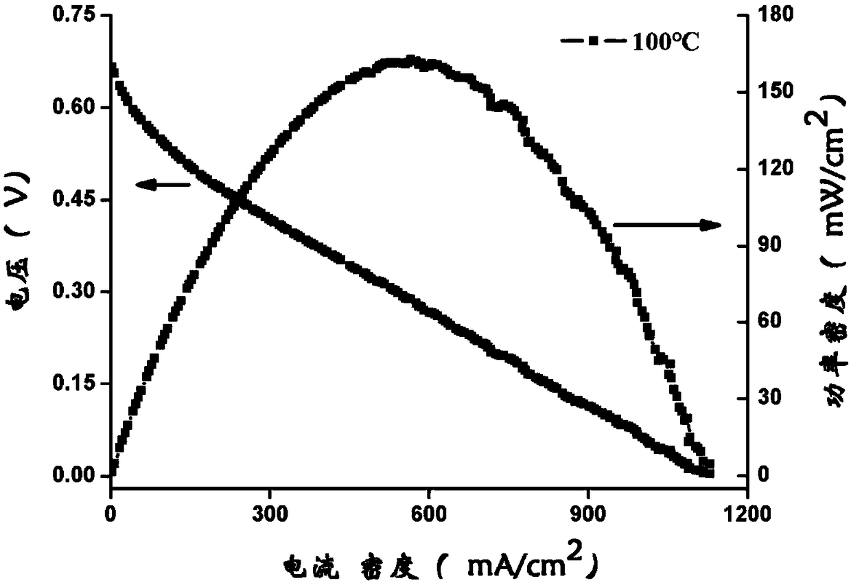
[0044] 3. Put the prepared ferrous iron anolyte and pentavalent vanadium catholyte into the anolyte tank and catholyte tank at 80°C respectively, and use a peristaltic pump to transport the anolyte and catholyte to the anode plate and cathode of the battery respectively board, and then use the electrochemical workstation to test the battery to detect the output voltage, current density, and power density of the battery. The results are as follows: image 3 As shown, the maximum output voltage of the battery prepared in Example 3 is 0.66mV, a...
PUM
| Property | Measurement | Unit |
|---|---|---|
| Concentration | aaaaa | aaaaa |
| Concentration | aaaaa | aaaaa |
| Current density | aaaaa | aaaaa |
Abstract
Description
Claims
Application Information
 - R&D
- Intellectual Property
- Life Sciences
- Materials
- Tech Scout
- Unparalleled Data Quality
- Higher Quality Content
- 60% Fewer Hallucinations
Browse by: Latest US Patents, China's latest patents, Technical Efficacy Thesaurus, Application Domain, Technology Topic, Popular Technical Reports.
© 2025 PatSnap. All rights reserved.Legal|Privacy policy|Modern Slavery Act Transparency Statement|Sitemap|About US| Contact US: help@patsnap.com


