
A high-speed permanent magnet motor rotor and its processing method

A technology for permanent magnet motors and rotors, which is applied in the direction of magnetic circuit rotating parts, manufacturing motor generators, manufacturing stator/rotor bodies, etc. It can solve the problems that it is difficult to withstand huge centrifugal force, the processing technology is difficult to meet, and the permanent magnet is difficult to bear. To achieve the effect of clear thinking, reasonable processing and strong heat dissipation

Active Publication Date: 2020-06-19
CRRC YONGJI ELECTRIC CO LTD
View PDF5 Cites 5 Cited by
  • Summary
  • Abstract
  • Description
  • Claims
  • Application Information

AI Technical Summary

Problems solved by technology

[0004] The purpose of the present invention is to solve the problems that conventional laminated rotors are difficult to withstand huge centrifugal force, permanent magnets are difficult to withstand the tensile stress generated by high-speed rotation of the rotor, the rotor is difficult to dissipate heat under high-speed rotation, and the traditional motor rotor processing technology is difficult to meet the quality requirements of high-speed motor rotors. problem, a high-speed permanent magnet motor rotor and its processing method are provided

Method used


Image

  • A high-speed permanent magnet motor rotor and its processing method
  • A high-speed permanent magnet motor rotor and its processing method

Examples


Embodiment Construction

[0024] In order to illustrate the embodiment of the present invention or the technical solution in the prior art more clearly, the technical solution of the present invention will be described in detail below. Apparently, the described embodiments are only some of the embodiments of the present invention, not all of them. Based on the embodiments of the present invention, all other implementations obtained by persons of ordinary skill in the art without making creative efforts fall within the protection scope of the present invention.

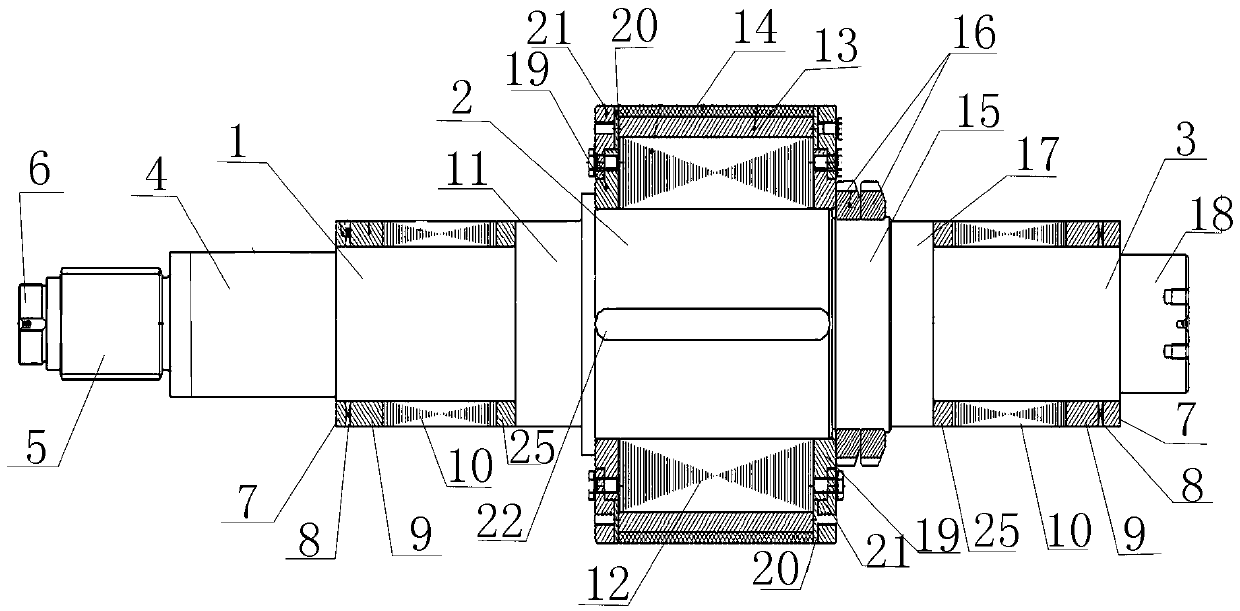
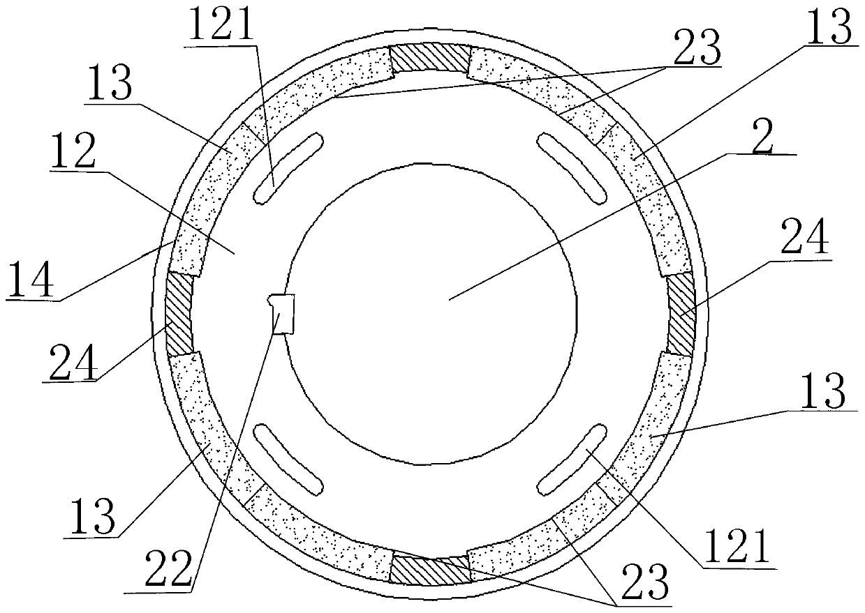
[0025] See attached figure 1 and 2 , a high-speed permanent magnet motor rotor and its processing method provided by the present invention will now be described.

[0026]A high-speed permanent magnet motor rotor, including a rotating shaft, the rotating shaft includes a first shaft body 1, a second shaft body 2 and a third shaft body 3 from left to right, and the diameter of the second shaft body 2 is larger than that of the first shaft body ...


PUM


Abstract

The invention belongs to the field of electric machines, in particular to a high-speed permanent magnet motor rotor and a processing method thereof, the high-speed permanent magnet motor rotor comprises a high-speed permanent magnet motor rotor, including a rotating shaft, the rotating shaft includes a first shaft body from left to right, a second shaft body and a third shaft body, A magnetic levitation bear sensor rotor assembly is provided on that first shaft body and the third shaft body, A maglev bearing sensor rotor silicon steel sheet, a maglev bearing rotor assembly and a maglev bearingrotor silicon steel sheet, a rotor iron core is sleeved on a second shaft body, a surface-mount permanent magnet is arranged on an outer periphery of that rotor iron core, and a carbon fiber sheath is wrapped on the outer periphery of the permanent magnet. The whole structure of the rotor of the invention is compact and reliable. Strong ability to resist radial tension and tangential stress; Effective protection of permanent magnets in permanent magnet motors; Strong heat dissipation ability; The processing method of the invention can reasonably and efficiently realize the processing of the high-quality high-speed permanent magnet motor rotor through the close cooperation between different steps.

Description

technical field [0001] The invention belongs to the field of motors, and relates to a motor rotor structure, in particular to a high-speed permanent magnet motor rotor and a processing method thereof. Background technique [0002] Permanent magnet motors have the advantages of high efficiency, high power factor, and large speed range. Therefore, permanent magnet motors are favored in high-speed applications. Compared with the outer permanent magnet rotor motor, the inner rotor permanent magnet motor has the advantages of small rotor radius and strong reliability, and has become the first choice for high-speed motors. [0003] The rotor speed of high-speed motors is usually higher than 10000r / min. When rotating at high speed: conventional laminated rotors are difficult to withstand huge centrifugal force. For permanent magnet motors, the problem of rotor strength is more prominent, because sintered permanent magnet materials cannot To withstand the tensile stress generated b...

Claims


Application Information

Patent Timeline
Patent Type & Authority Patents(China)
IPC IPC(8): H02K1/27H02K1/32H02K7/00H02K7/09H02K11/20H02K15/03
CPCH02K1/2706H02K1/32H02K7/003H02K7/09H02K11/20H02K15/03
Inventor 程铭贺志学段志强贾健黄娜
Owner CRRC YONGJI ELECTRIC CO LTD
Learn More