
Offshore non-adiabatic isobaric double-container compressed air energy storage system and method

A compressed air energy storage, dual-container technology, used in machines/engines, liquid variable-capacity machinery, pump control, etc. It is difficult to continue to apply and other problems, so as to reduce the corrosion effect, reduce the system cost, and improve the energy utilization efficiency.

Inactive Publication Date: 2018-12-14
XI AN JIAOTONG UNIV
View PDF5 Cites 3 Cited by
  • Summary
  • Abstract
  • Description
  • Claims
  • Application Information

AI Technical Summary

Problems solved by technology

With the development of wind energy resources gradually shifting to offshore, traditional compressed air energy storage technology is difficult to continue to apply to offshore conditions
At the same time, the compressors of the existing compressed air energy storage system all take in air from the air, and the air intake pressure is the ambient pressure
The compression process requires multi-stage compression and multi-stage cooling to meet energy storage requirements, and this process will cause a large amount of irreversible loss of electrical energy
Both the energy storage process and the energy release process of the traditional compressed air energy storage system operate under variable working conditions, which leads to a significant reduction in the energy storage and energy release conversion efficiency of the system

Method used


Image

  • Offshore non-adiabatic isobaric double-container compressed air energy storage system and method

Examples


Embodiment 1

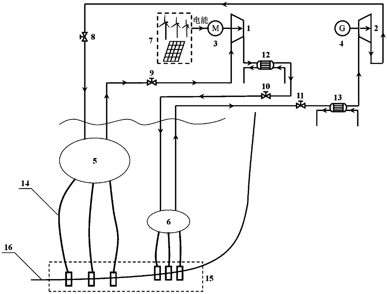
[0032] The marine non-adiabatic isobaric double-container compressed air energy storage system of the present invention, such as figure 1 As shown, the compressor unit 1, the expander unit 2, the electric motor 3, and the generator 4 are included.

[0033] The air inlet of the compressor unit 1 is connected with a motor 3 for driving its work, and the air inlet of the expander unit 2 is connected with a generator 4, and the motor 3 uses the electric energy from the wind farm / photovoltaic power station to drive the compressor unit 1 to do work.

[0034] The air inlet of the low pressure air bag 5 is connected to the air outlet of the expander unit 2 through the first electronic control valve 8, and the air outlet of the low pressure air bag 5 is connected to the air inlet of the compressor unit 1 through the second electronic control valve 9.

[0035] The air inlet of the high-pressure airbag 6 passes through the third electronically controlled valve 10 in turn to connect with the air...

Embodiment 2

[0045] A first heat exchanger 12 is installed between the gas outlet of each compressor and the gas inlet of the next compressor; a second heat exchanger 13 is installed before the gas inlet of each expander; the multi-stage compressor unit 1 and Inter-stage heat exchangers are installed between the stages of the multi-stage expander unit 2, so the gas compression and gas expansion processes are non-adiabatic processes.

[0046] During the low electricity consumption period, the offshore non-adiabatic isobaric double-container compressed air energy storage system of the present invention enters the energy storage process. When the second electric valve 9 and the third electric valve 10 are opened, the gas in the low-pressure airbag 5 whose pressure is higher than the standard atmospheric pressure is compressed by the compressor unit 1 and then cooled by the first heat exchanger 12 to enter the high-pressure airbag 6. When the gas pressure in the high-pressure airbag 6 reaches a c...


PUM


Abstract

The invention provides an offshore non-adiabatic isobaric double-container compressed air energy storage system and method. A motor for driving a compressor unit to do work is connected to a power input end of the compressor unit. A generator is connected to a power output end of an expander unit. A valve of a gas inlet of a low-pressure gas bag is connected with a gas outlet of the expander unit,and a valve of a gas outlet of the low-pressure gas bag is connected with a gas inlet of the compressor unit. A valve of a gas inlet of a high-pressure gas bag is connected with a gas outlet of the compressor unit, and a valve of a gas outlet of the high-pressure gas bag is connected with a gas inlet of the expander unit. The low-pressure gas bag and the high-pressure gas bag are both arranged below the sea surface with the depths unchanged. When energy is stored, the motor drives the compressor unit to do work, and gases in the low-pressure gas bag enter the high-pressure gas bag; and when the energy is released, the high-pressure gases in the high-pressure gas bag do work on the expander unit and drive the generator to generate electricity, and the gases that complete the work enter thelow-pressure gas bag. The compression process is significantly shortened and the energy utilization efficiency of the energy storage system is improved.

Description

Technical field [0001] The invention relates to the technical field of physical energy storage, in particular to an offshore non-adiabatic isostatic double-container compressed air energy storage system and method. Background technique [0002] With the improvement of the country's environmental standards and the people's demand for quality of life, the high pollution and high emissions caused by the long-term consumption of fossil fuels have received more and more attention, and the adjustment and optimization of energy structure has risen to the national strategic level. Therefore, the development of renewable energy continues to increase, and the proportion of clean energy such as wind power and solar energy in the primary energy continues to increase. Due to the volatility of the natural temporal and spatial distribution of renewable energy such as wind and solar energy, the increase in the proportion of renewable energy in the energy structure puts forward higher requirement...

Claims


Application Information

Patent Timeline
Patent Type & Authority Applications(China)
IPC IPC(8): F04B41/02F04B35/04F04B49/22F01D15/10
CPCF01D15/10F04B35/04F04B41/02F04B49/22Y02E60/16
Inventor 王焕然严凯李丞宸刘明明张淑宇李瑞雄
Owner XI AN JIAOTONG UNIV
Learn More