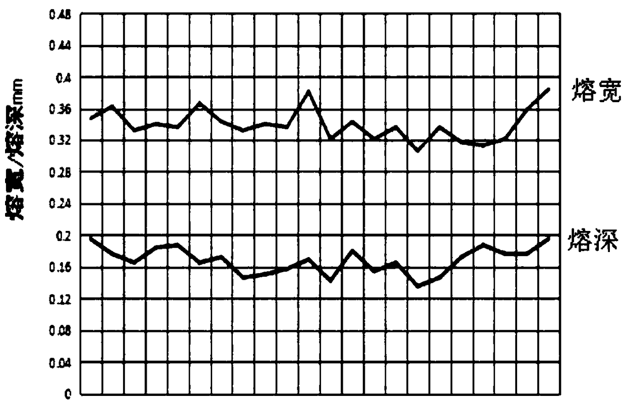
Fusion depth and fusion width detection method for thin-wall material welding face
A detection method and welding surface technology, which is applied in welding equipment, auxiliary welding equipment, welding/cutting auxiliary equipment, etc., can solve the problems of not being able to truly and accurately reflect the welding quality of the weld seam of materials, and achieve the effect of simple and efficient operation
- Summary
- Abstract
- Description
- Claims
- Application Information
AI Technical Summary
Problems solved by technology
Method used
Image
Examples
Embodiment 1
[0053] This embodiment provides a method for detecting the penetration depth and fusion width of the welded surface of a thin-walled material. Put the igniter into the airtight detonator, detonate it under the condition of 1.2A constant current direct current, select the remnant shell of the igniter, and implement according to the following steps:
[0054] Step 1. Cut the residual casing to be tested, clean the cutting surface after cutting, and obtain the residual casing
[0055] Step 1.1. Put the remaining shells to be tested into the cutting machine mold, 5 pieces at a time, switch the cutting machine operation and water adding mode to automatic, and run the cutting machine;
[0056] Step 1.2, after cutting by the cutting machine, the primary shell fragments are obtained, and the primary shell fragments are taken out with tweezers;
[0057] Step 1.3: Clean the cut surface of the primary shell fragment with alcohol until the surface is clean, and then blow it dry to obtain ...
Embodiment 2
[0075] This embodiment provides a method for detecting the penetration depth and fusion width of the welding surface of a thin-walled material. Put the igniter into the airtight detonator, detonate it under the condition of 1.19A constant current direct current, select the shell of the igniter, and implement it according to the following steps:
[0076] Step 1. Cut the residual casing to be tested, clean the cutting surface after cutting, and obtain the residual casing
[0077] Step 1.1. Put the residual casing to be tested into the cutting machine mold, one piece at a time, switch the cutting machine operation and water adding mode to automatic, and run the cutting machine;
[0078] Step 1.2, after cutting by the cutting machine, the primary shell fragments are obtained, and the primary shell fragments are taken out with tweezers;
[0079] Step 1.3: Clean the cut surface of the primary shell fragment with alcohol until the surface is clean, and then blow it dry to obtain the...
Embodiment 3
[0096] This embodiment provides a method for detecting the penetration depth and fusion width of the welding surface of a thin-walled material. Put the igniter into the airtight detonator, detonate it under the condition of 1.21A constant current direct current, select the shell of the igniter, and follow the steps below:
[0097] Step 1. Cut the residual casing to be tested, clean the cutting surface after cutting, and obtain the residual casing
[0098] Step 1.1. Put the remaining shells to be tested into the cutting machine mold, 4 pieces at a time, switch the cutting machine operation and water adding mode to automatic, and run the cutting machine;
[0099] Step 1.2, after cutting by the cutting machine, the primary shell fragments are obtained, and the primary shell fragments are taken out with tweezers;
[0100] Step 1.3: Clean the cut surface of the primary shell fragment with alcohol until the surface is clean, and then blow it dry to obtain the shell fragment.
[01...
PUM
| Property | Measurement | Unit |
|---|---|---|
| depth | aaaaa | aaaaa |
Abstract
Description
Claims
Application Information
 - R&D
- Intellectual Property
- Life Sciences
- Materials
- Tech Scout
- Unparalleled Data Quality
- Higher Quality Content
- 60% Fewer Hallucinations
Browse by: Latest US Patents, China's latest patents, Technical Efficacy Thesaurus, Application Domain, Technology Topic, Popular Technical Reports.
© 2025 PatSnap. All rights reserved.Legal|Privacy policy|Modern Slavery Act Transparency Statement|Sitemap|About US| Contact US: help@patsnap.com

