
Working method of punching and cutting all-in-one machine for C-type steel of steel support

A working method and technology for C-shaped steel, applied in the field of punching and cutting integrated machine for steel bracket C-shaped steel, can solve the problems of low production efficiency, large labor demand, low hole position accuracy, etc., to improve production efficiency and automation. High, reduced footprint effect

Active Publication Date: 2018-12-18
包头市正林钢构彩板有限公司
View PDF6 Cites 19 Cited by
  • Summary
  • Abstract
  • Description
  • Claims
  • Application Information

AI Technical Summary

Problems solved by technology

As a kind of steel component, the existing steel bracket C-shaped steel has excellent mechanical properties and superior service performance. The steel structure mainly made of steel bracket C-shaped steel has a high degree of industrialization, which is convenient for mechanical manufacturing, intensive production, and high precision. , easy to install, and easy to guarantee quality, and is widely used in the field of construction engineering. C-shaped steel needs to be cut and punched in the process of processing for the subsequent production and assembly of steel structures. The existing ones are generally done manually. Manual and semi-mechanized cutting and punching operations are time-consuming and labor-intensive, requiring a large amount of labor, and the cutting size and hole position accuracy are low, resulting in low production efficiency

Method used


Image

  • Working method of punching and cutting all-in-one machine for C-type steel of steel support
  • Working method of punching and cutting all-in-one machine for C-type steel of steel support
  • Working method of punching and cutting all-in-one machine for C-type steel of steel support

Examples


Embodiment Construction

[0030] The following will be combined with Figure 1 to Figure 8 The present invention is described in detail, and the technical solutions in the embodiments of the present invention are clearly and completely described. Apparently, the described embodiments are only some of the embodiments of the present invention, not all of them. Based on the embodiments of the present invention, all other embodiments obtained by persons of ordinary skill in the art without making creative efforts belong to the protection scope of the present invention.

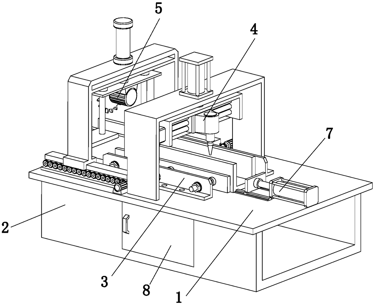
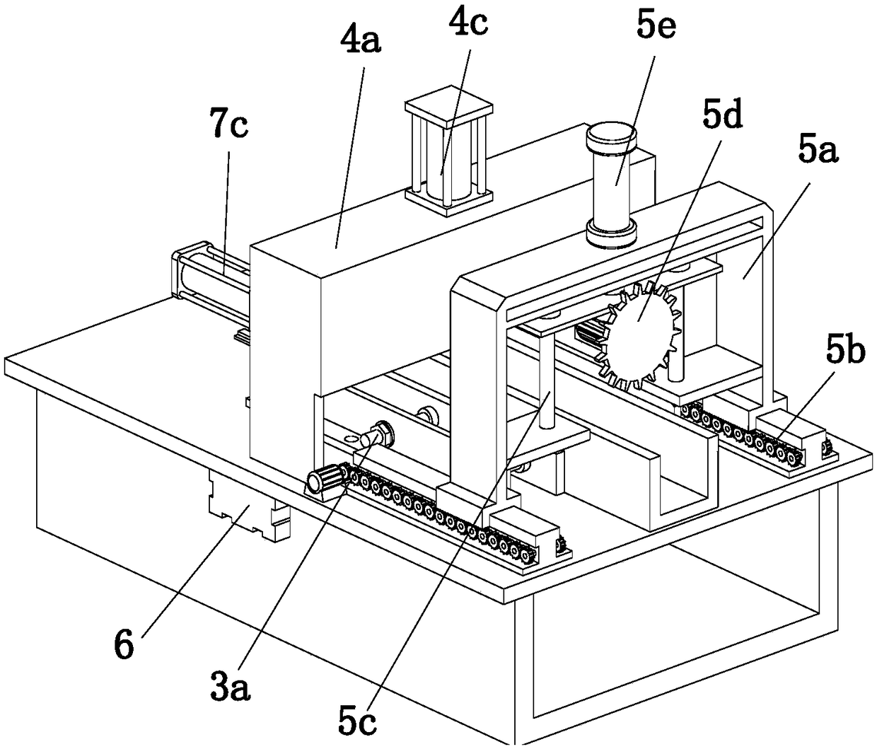
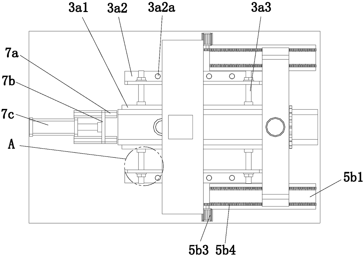
[0031]The present invention provides a punching and cutting integrated machine for steel bracket C-shaped steel through improvement, such as Figure 1-Figure 8 As shown, it includes a horizontally arranged workbench 1 and a U-shaped support plate 2 fixedly connected to the bottom of the workbench 1. The top of the workbench 1 is respectively provided with an adjustment and positioning device 3 for limiting the C-shaped steel. A punching d...


PUM


Abstract

The invention relates to the field of steel structure machining, in particular to a working method of a punching and cutting all-in-one machine for C-type steel of a steel support. The punching and cutting all-in-one machine comprises a workbench and a U-shaped supporting plate. An adjustment positioning device, a punching device and a cutting device are arranged at the top of the workbench. An adjustment connecting device is arranged at the bottom of the workbench. A driving device is arranged at the top of the workbench. The adjustment positioning device comprises two limiting assemblies which are symmetrically arranged at the top of the workbench. The punching device comprises a first portal frame, a punching assembly and a first driving assembly. The two bottom ends of the first portalframe are separately located on one sides of the two limiting assemblies, and the first portal frame is vertically mounted at the top of the workbench. The punching assembly is mounted on the first driving assembly. The first driving assembly is mounted on the first portal frame. A door plate which can be opened is arranged on the side wall of the U-shaped supporting frame. The punching and cutting all-in-one machine is simple in structure; punching and cutting are integrated, so that the occupied area is reduced; and the automation degree is high, the production efficiency is improved, and the labor intensity of workers is relieved.

Description

technical field [0001] The invention relates to the field of steel structure processing, in particular to a working method of a punching and cutting integrated machine for steel bracket C-shaped steel. Background technique [0002] With the rapid development of economic construction, a large number of steel components are used in building construction, railway construction and other industries. Steel components refer to steel plates, angle steels, channel steels, I-beams, welded or hot-rolled H-beams that are cold-bent or welded through connectors The connected steel structure composite members that can bear and transmit loads. The steel component system has comprehensive advantages such as light weight, factory manufacturing, fast installation, short construction period, good seismic performance, fast investment recovery, and less environmental pollution. With the unique advantages of development in three aspects, steel components have been reasonably and widely used in th...

Claims


Application Information

Patent Timeline
IPC IPC(8): B23P23/00B21D28/34B21D43/20
CPCB21D28/34B21D43/20B23P23/00
Inventor 何红侠苏波姚巧宁
Owner 包头市正林钢构彩板有限公司
Learn More