Spherical suspended bio-filler

A bio-filler, spherical technology, applied in the field of fillers, can solve the problems of not easy to hang the film, increase the cost of sewage treatment, small specific surface area, etc.

Inactive Publication Date: 2018-12-18
ZHEJIANG WORLD CLEAN ENVIRONMENT ENG CO LTD
View PDF6 Cites 5 Cited by
  • Summary
  • Abstract
  • Description
  • Claims
  • Application Information

AI Technical Summary

Problems solved by technology

[0003] However, the specific surface area of ​​the existing filler balls is small and it is not easy to hang a film. When more mi

Method used


Image

  • Spherical suspended bio-filler
  • Spherical suspended bio-filler

Examples


Embodiment 1

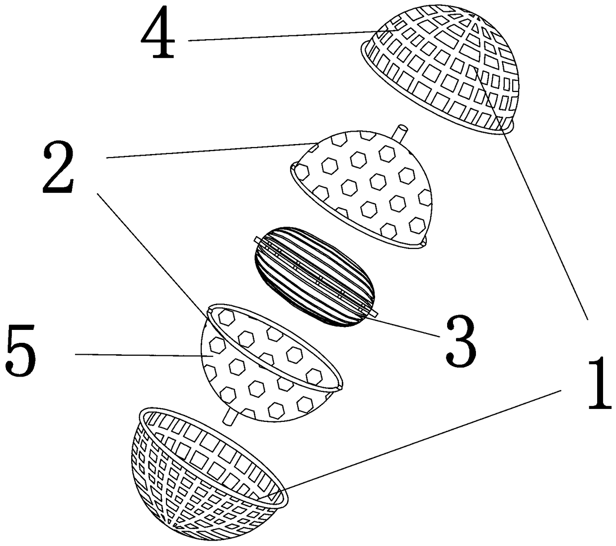
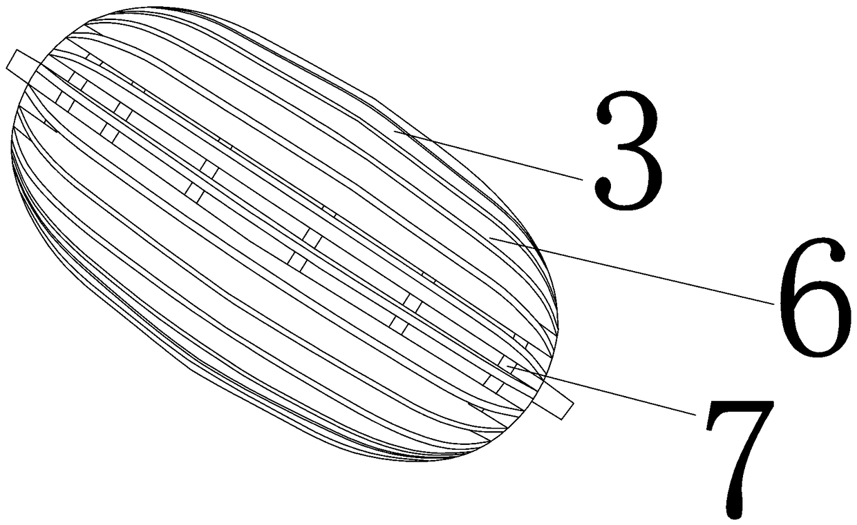
[0022] Such as Figure 1-Figure 2 As shown, a spherical suspended biological filler provided in this embodiment includes a spherical suspended biological filler, including a spherical shell 1, and a spherical body 2 that can rotate longitudinally is sleeved in the shell 1, and the The sphere 2 is sleeved with an ellipsoid 3 that can rotate laterally; the shell 1 is provided with hollow holes 4 , the sphere 2 is provided with hollow holes 5 , and the ellipsoid 3 is provided with fins. fins 6, and through grooves 7 are distributed between each fin 6.

[0023] The material of the shell 1, the spherical body 2 and the ellipsoid 3 is modified polypropylene.

[0024] The modified polypropylene is prepared by coating the surface of the polypropylene with a hydrophilic agent, and the hydrophilic agent includes 5 parts of nano silicon dioxide, 10 parts of alkylphenol polyoxyethylene ether, carbon nano 1 part of tube, 10 parts of polyvinyl chloride, 50 parts of ethanol, 10 parts of is...

Embodiment 2

[0028] The general structure of the spherical suspended biological filler provided in this embodiment is the same as that of the embodiment, the difference being that the material of the shell 1, the spherical body 2 and the ellipsoid 3 is modified polyethylene.

[0029] The modified polyethylene includes 95 parts of polyethylene and 5 parts of modifying agent by weight, and the modifier includes 50 parts of polyacrylate, 20 parts of polyethylene glycol, 10 parts of polyvinylidene fluoride, 5 parts of polyurethane, 2 parts of zirconium phosphate, and 1 part of rare earth.

[0030] The preparation method of the modifier is to put 50 parts of polyacrylate, 20 parts of polyethylene glycol, 10 parts of polyvinylidene fluoride, 5 parts of polyurethane, 2 parts of zirconium phosphate and 1 part of rare earth into 200-240 parts by weight. In a high-temperature reaction furnace at ℃, heat for 1-2 hours under the protection of nitrogen, and grind it into powder after cooling.

[0031]...

Embodiment 3

[0034] A spherical suspended biological filler provided in this embodiment has the same general structure as that of the embodiment, the difference being that the material of the shell 1 and the spherical body 2 is modified polypropylene, and the material of the ellipsoid 3 is modified polyethylene .

[0035] The modified polypropylene is prepared by coating the surface of the polypropylene with a hydrophilic agent, and the hydrophilic agent includes 10 parts by weight of nano silicon dioxide, 15 parts of alkylphenol polyoxyethylene ether, carbon nano 5 parts of tube, 15 parts of polyvinyl chloride, 60 parts of ethanol, 15 parts of isopropanol, and 40 parts of water.

[0036] The modified polyethylene includes 95 parts of polyethylene and 5 parts of modifying agent by weight, and the modifier includes 60 parts of polyacrylate, 30 parts of polyethylene glycol, 15 parts of polyvinylidene fluoride, 8 parts of polyurethane, 3 parts of zirconium phosphate, and 3 parts of rare eart...


PUM

PropertyMeasurementUnit
Proportionaaaaaaaaaa

Abstract

The invention discloses a spherical suspended bio-filler. The spherical suspended bio-filler comprises a spherical shell, a longitudinally rotatable sphere is jointed in the shell, and a transverselyrotatable ellipsoid is jointed in the sphere; and hollow-out holes are distributed in the shell, hollow-out small holes are distributed in the sphere, fins are distributed on the ellipsoid, and through grooves are distributed between the adjacent fins. The spherical suspended bio-filler obtained in the invention comprises the shell, the sphere and the ellipsoid from the outside to the inside, wherein the sphere can rotate longitudinally, and the ellipsoid can rotate transversely. Three spheres are arranged to increase the fluidity, and especially the fins of the ellipsoids are arranged to increase the specific surface area of the filler sphere. Additionally, the material of the shell, the sphere and the ellipsoid is any one of modified polypropylene and modified polyethylene in order torealize strong hydrophilicity and easy bio-film formation.

Description

technical field [0001] The invention relates to a filler, in particular to a spherical suspended biological filler. Background technique [0002] At present, biological filler balls are placed in the sewage that needs to be treated, through which the organic matter and impurities in the sewage are separated from the water. That is to say, when the water with dirt flows through the filler balls, the organic matter and impurities in the water are attached to the filler balls, and then these organic matter and impurities react with the microorganisms on the filler until they are decomposed into harmless substances to achieve The purpose of water purification, such as: to eliminate ammonia and nitrogen in water. [0003] However, the specific surface area of ​​the existing filler balls is small and it is not easy to hang a film. When more microorganisms need to be attached, it can only be achieved by increasing the number, which increases the cost of sewage treatment. Content...

Claims


Application Information

Patent Timeline
IPC IPC(8): C02F3/10C02F3/00
CPCC02F3/00C02F3/107C02F3/108C02F3/109Y02W10/10
Inventor 陈宽陈勇
Owner ZHEJIANG WORLD CLEAN ENVIRONMENT ENG CO LTD
Why Eureka
Try Eureka