Mold pouring molding wound inductor and preparation method thereof

A wire-wound inductor and infusion molding technology, which is applied in the field of inductors, can solve problems affecting the welding of inductors and PCBs, limited external impact force, damage, etc., to improve the ability to withstand DC superposition Isat, reduce the fullness, The effect of reducing the DC resistance

Pending Publication Date: 2018-12-18
CYGE ELECTRONIC TECH (HUNAN) CO LTD
View PDF0 Cites 9 Cited by
  • Summary
  • Abstract
  • Description
  • Claims
  • Application Information

AI Technical Summary

Problems solved by technology

[0002] At present, the soft magnetic core material used in semi-shielded magnetic glue wound inductors is nickel-zinc ferrite material or alloy iron-silicon-chromium material. The process uses a precision dispenser to evenly coat the mixed magnetic glue on the wound inductor The magnetic shielding of the inductance coil is realized in the wide area of ​​the wrapping wire; at present, the soft magnetic material is nickel-zinc ferrite material or alloy iron-silicon-chromium material, because the initial magnetic permeability of nickel-zinc ferrite material or alloy iron-silicon-chromium material is low , high coercive force; high material loss; more coils need to be wound in the production of wire-wound inductors, leading to a rather long length of winding enameled wire, so the winding DC impedance is high, and the final product generates heat when it is energized Large, low efficiency; and the number of coil windings is large, resulting in a relatively full inductance wire package. When the magnetic glue is applied, it is easy to form a vertical flow of glue, which affects the welding between the inductor and the PCB; at the same time, due to the exposed soft magnetic core, the affected The external impact force is limited, and the magnetic core body is prone to chipping and damage

Method used


Image

  • Mold pouring molding wound inductor and preparation method thereof
  • Mold pouring molding wound inductor and preparation method thereof
  • Mold pouring molding wound inductor and preparation method thereof

Examples


Embodiment Construction

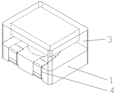
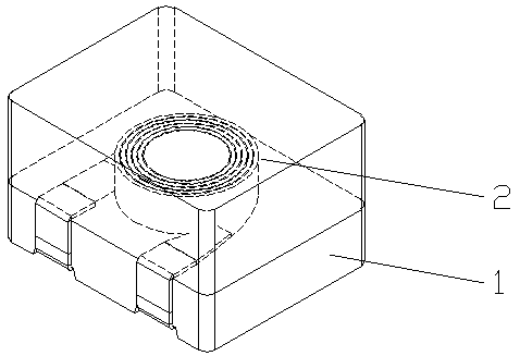
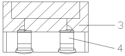
[0018] Below in conjunction with all accompanying drawings the present invention will be further described, and preferred embodiment of the present invention is: see appended figure 1 to attach Figure 22 , the preparation method of the mold injection molded wire wound inductor described in the present embodiment includes the following steps, prefabricating the soft magnetic core-soft magnetic core outer coating layer treatment-soft magnetic core terminal electrode formation-coil wire roll Winding, spot welding—fixture filling with magnetic glue—glue drying—lower fixture—external inspection—printing—testing, and it’s done. The fixture filling with magnetic glue is to first place the product in the fixture, then pour the magnetic glue, and then Take out the product from the jig, which is as follows: inject the prepared magnetic glue into the hole of the jig with a precision dispensing machine, and then put the solder surface of the inductance device with the enameled wire upsid...


PUM


Abstract

The invention provides a preparation method of a mold pouring molding wound inductor, It comprises the following steps, A prefabricated soft magnetic core-soft magnetic core outer coating treatment-soft magnetic core terminal electrode formation-coil wire winding, spot welding-fixture pouring magnetic glue-drying glue-lower fixture-external inspection-printing-test, That is, the soft magnetic Mn-Zn ferrite material is adopted as the winding body, the Mn-Zn ferrite material has relatively high initial magnetic permeability, the initial magnetic permeability of the Mn-Zn ferrite material is morethan 5 times of the initial magnetic permeability of the Ni-Zn ferrite material, and the eddy current loss of the Mn-Zn ferrite material is small, and the quality factor is high.

Description

technical field [0001] The invention relates to an inductor, in particular to a wire-wound inductor molded by mold injection and a preparation method thereof. Background technique [0002] At present, the soft magnetic core material used in semi-shielded magnetic glue wound inductors is nickel-zinc ferrite material or alloy iron-silicon-chromium material. The process uses a precision dispenser to evenly coat the mixed magnetic glue on the wound inductor The magnetic shielding of the inductance coil is realized in the wide area of ​​the wrapping wire; at present, the soft magnetic material is nickel-zinc ferrite material or alloy iron-silicon-chromium material, because the initial magnetic permeability of nickel-zinc ferrite material or alloy iron-silicon-chromium material is low , high coercive force; high material loss; more coils need to be wound in the production of wire-wound inductors, leading to a rather long length of winding enameled wire, so the winding DC impedance...

Claims


Application Information

Patent Timeline
Patent Type & Authority Applications(China)
IPC IPC(8): H01F27/02H01F27/24H01F27/29H01F27/32H01F27/34H01F1/37H01F41/00H01F41/02
CPCH01F27/34H01F1/37H01F27/022H01F27/24H01F27/292H01F27/324H01F41/00H01F41/005H01F41/0246H01F2027/348
Inventor 苏立良
Owner CYGE ELECTRONIC TECH (HUNAN) CO LTD
Why Eureka
Try Eureka