Gasification combustion furnace with low-temperature desaccharification

A combustion furnace and sugar removal technology, applied in the field of boilers, can solve the problems affecting the heating and heat transfer of the boiler, reduce the service life of the boiler, and cannot be removed, and achieve the effects of secondary utilization, cost saving, and reduction of the probability of blasting.

Pending Publication Date: 2018-12-21
张青林
View PDF0 Cites 0 Cited by
  • Summary
  • Abstract
  • Description
  • Claims
  • Application Information

AI Technical Summary

Problems solved by technology

[0002] As a kind of heat energy supply equipment, boilers are widely used in electric power, machinery, metallurgy, chemical industry, textile, papermaking, food, industrial and civil heating, and the fuels used by existing boilers generally include coal, straw, diesel, natural gas, petroleum gas, etc. etc. According to the different fuels used, boilers can be divided into three types: solid fuel boilers, liquid fuel boilers and gas fuel boilers. Among them, biomass straw boilers are a kind of solid fuel boilers. Due to their low cost, relatively safe heating and environmental pro...

Method used


Image

  • Gasification combustion furnace with low-temperature desaccharification
  • Gasification combustion furnace with low-temperature desaccharification
  • Gasification combustion furnace with low-temperature desaccharification

Examples


Embodiment 1

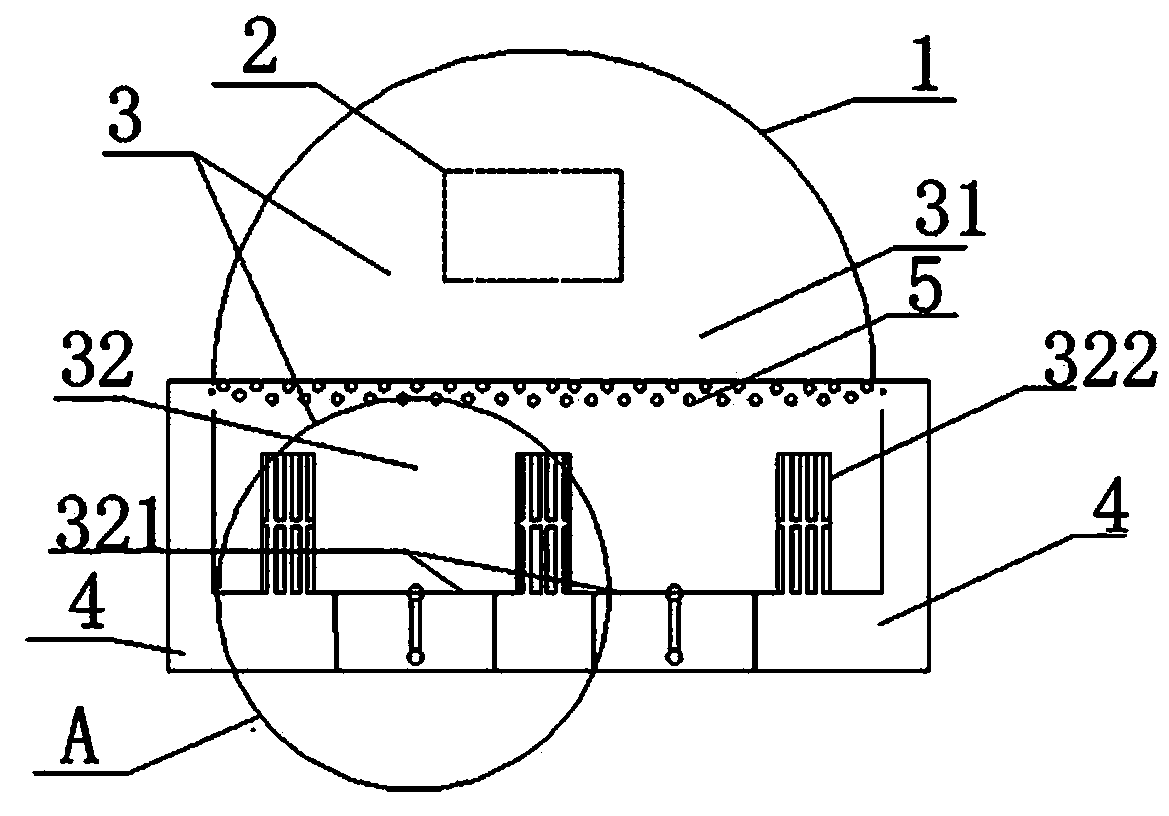
[0041] Such as figure 1 , Figure 4 The shown low-temperature desugar combustion furnace includes two parts: a furnace body 1 and an induced draft fan 2. Preferably, an explosion-proof nozzle 1c is provided outside the furnace body 1, and the explosion-proof nozzle 1c has the function of adjusting the pressure in the furnace. When deflagration occurs inside the furnace body 1 , when the pressure inside the furnace body 1 rises rapidly, the explosion-proof nozzle 1c automatically releases the pressure in the furnace to prevent the furnace body 1 from exploding due to the deflagration pressure. Port 1a communicates with combustion zone 2 32. The opening direction of feed port 1a is preferably between 0-90° to the vertical direction. Feed port 1a is convenient for putting straw fuel into furnace body 1. The outer side of the bottom of the furnace body communicates with the waste material chamber 6, and a flat furnace door can be selected to facilitate cleaning out the burned was...

Embodiment 2

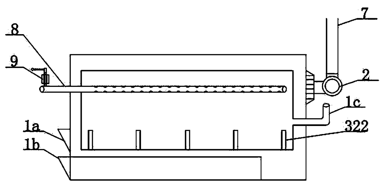
[0060] Such as figure 2 As shown in , the technical solution of this embodiment can refer to the technical solution of embodiment 1, and the body of furnace structure in this embodiment can also refer to the body of furnace structure in embodiment one, but the structure of body of furnace 1 in the present embodiment and implementation The difference of body of furnace 1 structure in example one is: as figure 2 The low-temperature desugaring combustion furnace shown also includes: air duct three 8 and air valve 9, air duct three 8 is inserted on furnace body 1, and communicates combustion zone one 31 with the atmosphere outside furnace body 1, air duct three 8 is located at The part in the combustion zone-31 can choose flower tube structure, open the through hole near the position of gas injection hole 5, the number of through holes can be multiple, it is arranged in this way while increasing the ventilation rate, it also helps to disperse and evenly supply the air. To preve...

Embodiment 3

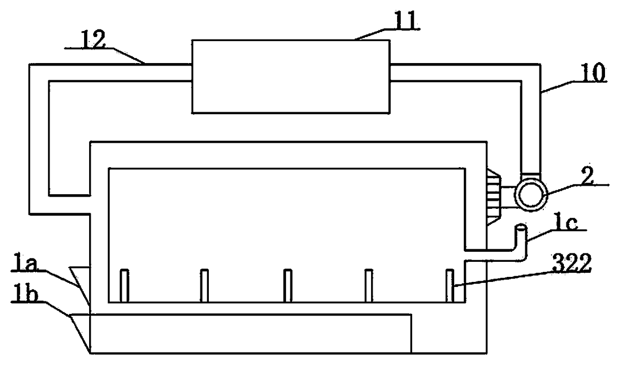
[0075] Such as image 3 As shown in , the technical solution of this embodiment can refer to the technical solution of embodiment 1, and the body of furnace structure in this embodiment can also refer to the body of furnace structure in embodiment one, but the structure of body of furnace 1 in the present embodiment and implementation The difference of body of furnace 1 structure in example one is: as image 3 As shown in the low-temperature desugar combustion furnace, there are flue one 7, smoke box 8, and flue two 9 outside the furnace body 1. The air inlet of the induced draft fan 2 is connected to the air duct one 3 in the furnace body 1, and the air outlet is connected to the flue one. 7 is connected, flue one 7, flue two 9 one end is communicated with air duct one 3 in body of heater 1, and the other end connects smoke box. The smoke box 8 is located outside the furnace body 1, and communicates with the first flue 7 and the second flue 9. The air duct one 4, the induce...


PUM


Abstract

The invention discloses a gasification combustion furnace with low-temperature desaccharification, which is characterized by comprising a furnace body and an induced draft fan. The induced draft fan is arranged on the furnace body, and communicates with the interior of the furnace body. The interior of the furnace body is provided with a combustion area, air ducts 1, air ducts 2, and gas injectionholes. The air ducts 1 are arranged below the bottom of the combustion area, and communicate with the combustion area through the air ducts 2 uniformly arranged at the bottom of the combustion area.The gas injection holes are arranged on the inner wall of the furnace body in the combustion area. The combustion area comprises a combustion area 1 and a combustion area 2. The combustion area 1 is an area enclosed by the inner wall of the furnace body corresponding to the gas injection holes, and communicates with the combustion area 2 through the gas injection holes. The bottom of the combustion area 2 is a fire grate, and the side wall is composed of the air ducts 2 and the inner wall of the furnace body. The combustion area 2 and the air ducts 1 are separately communicate with the air ducts 2. The outer side bottom face and the side face of the combustion area 2 are circularly provided with the air ducts 1. The induced draft fan communicates with the combustion area 1. According to the gasification combustion furnace with the low-temperature desaccharification, the problems of fuel carbonization and heat supply are solved, and the service life of a boiler is prolonged by changingthe direct combustion mode of the boiler.

Description

technical field [0001] The invention relates to a boiler, in particular to a low-temperature desugar gasification combustion furnace. Background technique [0002] As a kind of heat energy supply equipment, boilers are widely used in electric power, machinery, metallurgy, chemical industry, textile, papermaking, food, industrial and civil heating, and the fuels used by existing boilers generally include coal, straw, diesel, natural gas, petroleum gas, etc. etc. According to the different fuels used, boilers can be divided into three types: solid fuel boilers, liquid fuel boilers and gas fuel boilers. Among them, biomass straw boilers are a kind of solid fuel boilers. Due to their low cost, relatively safe heating and environmental protection, etc. The advantage has become an environmentally friendly stove with straw as the main fuel advocated by the state in recent years. However, the technical bottleneck of the existing straw boilers lies in the fact that straw, especially ...

Claims


Application Information

Patent Timeline
IPC IPC(8): F23B90/06
CPCF23B90/06
Inventor 张青林张文鹏
Owner 张青林
Why Eureka
Try Eureka